The operating envelope matters more than a noise label
A full-floating journal bearing needs more than oil pressure on a dashboard gauge. Its two oil films must receive clean oil, remove heat and control rotor motion through changing speed and load. A change in sound can reflect a change in this motion, but it can also come from an air leak, wheel damage or another fault.
This guide focuses on operating conditions and failure-relevant behaviour. For the bearing arrangement itself, start with how floating ring bearings work in turbochargers. The practical question here is whether the films still separate the surfaces and keep motion within the turbo's design limits.
The animation uses our in-house rotor-bearing model, running a nonlinear transient simulation from 20,000 to approximately 101,000 rpm on two floating ring bearings. Rotor and bearing data come from the published test turbocharger rotor of Eling's 2018 TU Delft PhD thesis, Towards robust design optimization of automotive turbocharger rotor-bearing systems. The replay is our simulation, not Eling's measured run-up and not testing or certification of any LeadTurbo product.
What the run-up shows
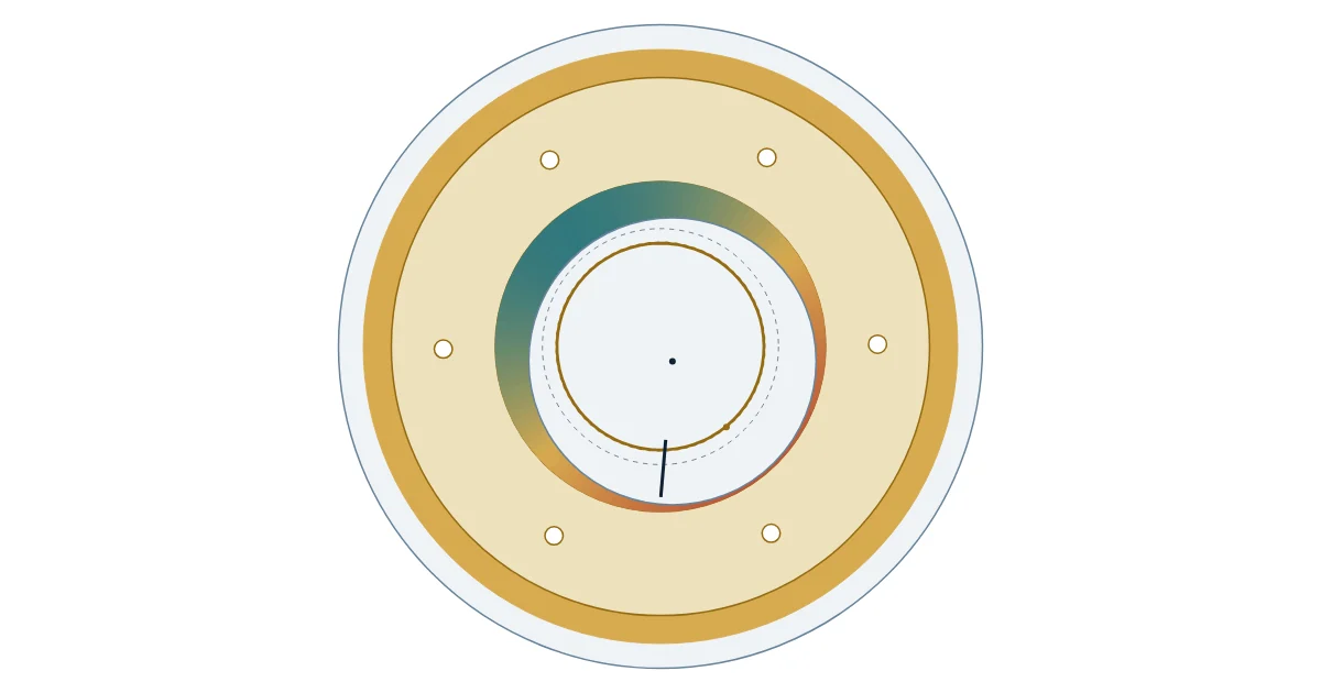
Eccentricity ratio, ε, is centre offset divided by radial clearance. Inner ε describes the journal relative to the ring; outer ε describes the ring relative to the housing. Zero means concentric, while one is the geometric clearance boundary. These are different motions, so a quiet outer film does not prove that the journal is nearly centred inside the ring.
| Shaft speed in this simulation | Inner-film eccentricity | Interpretation of this run |
|---|---|---|
| About 20–30 krpm | Near zero | Low-amplitude, stable region |
| About 33–52 krpm | About 0.7–0.9 | First inner-film oil whirl: a large sub-synchronous journal orbit inside the ring |
| About 52–78 krpm | About 0.02–0.12 | Return to a small inner orbit |
| From about 78 krpm | About 0.97–0.98 | Second whirl region, with the orbit close to the ring bore |
Outer-film eccentricity stays at or below approximately 0.06, and ring speed ratio is about 0.10–0.27 of shaft speed. These bands describe this calculation; they are not service limits or speed restrictions for other turbos. Transition speeds are approximate.
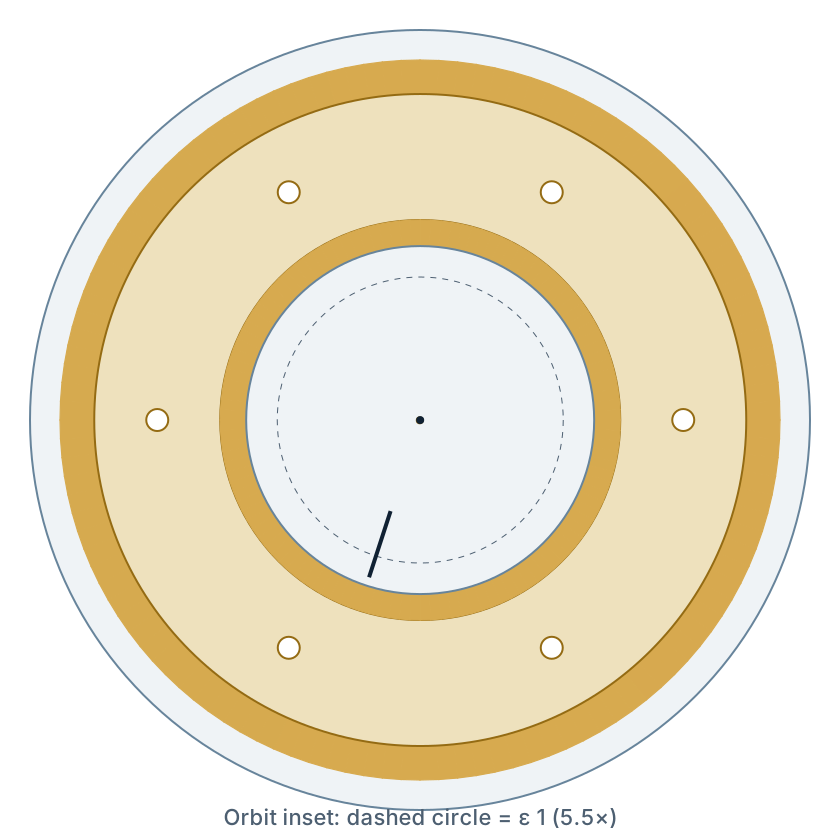
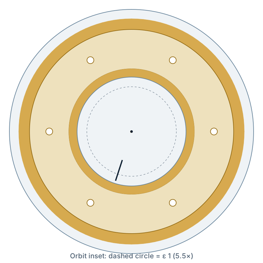
The model uses inner radial clearance of approximately 10 µm and outer radial clearance of approximately 28.5 µm. Displayed gaps are heavily exaggerated and not to scale. Colour indicates relative film thickness, not oil temperature. The orbit inset is enlarged separately.
Each of 24 speed points replays 300 samples covering a 30 ms window, slowed for viewing. The 0.1 ms sampling makes the shaft-angle marker step at high speed: that is sampling, not vibration. The trend shows mean and maximum eccentricity and mean ring speed ratio for approximately 0.5 s simulation blocks. Neither the orbit nor this trend alone is a frequency spectrum.
Bearing 1 (b0)
- Inner ε
- 0.004
- Outer ε
- 0.008
- Ring / shaft
- 0.206
Bearing 2 (b1)
- Inner ε
- 0.004
- Outer ε
- 0.008
- Ring / shaft
- 0.206
The gold ring rotates inside the housing. The journal moves inside the ring; the dark line marks shaft angle.
The journal-centre orbit is shown again at 5.5× the displayed displacement scale. Its dashed circle marks ε = 1.
How the two bearings respond to speed
Inner ε: gold, with shading to the block maximum. Outer ε: teal, with shading to its maximum. Ring speed ratio: dashed navy. Blocks cover approximately 0.5 s.
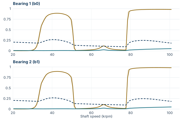
Select a speed with the slider or − / + buttons, or select a point on the chart. On narrow screens, scroll the chart sideways to see all speeds. Readings show instantaneous ε and the nearest trend block's mean ring speed ratio.
Our in-house simulation of Eling's published test rotor; no LeadTurbo product certification. Clearances are heavily exaggerated, not to scale. At high speed the shaft marker steps because samples are 0.1 ms apart. The orbit inset has its own scale. Small-orbit / whirl labels describe this replay, not acceptance criteria. JavaScript is optional: the static trend and article explain the result.
Oil whirl, oil whip and a bounded limit cycle
Oil-film forces can feed energy into lateral rotor motion, producing sub-synchronous vibration: an orbit slower than shaft rotation. For inner-film whirl with a rotating ring, a useful approximation is f_whirl ≈ (f_shaft + f_ring) / 2, with both rotational frequencies in the same units. It is not invariably half shaft speed. Eling describes this inner-film response, while Automotive Turbocharger Rotordynamics, second edition, expresses the relationship using a condition-dependent whirl ratio.
As speed rises, a whirl can couple to a rotor-bearing mode and stay near that mode's frequency. This is oil whip. A nearly constant tone during a speed sweep is therefore worth investigating, but sound alone cannot identify the mechanism. See oil whirl and oil whip explained for the frequency distinction.
Why can a floating bearing keep operating after whirl starts? Nonlinear film forces and damping can balance the energy entering the motion, giving a bounded limit cycle instead of indefinitely growing vibration. San Andrés, Naranjo and Holt report such behaviour experimentally. Stability of that repeating orbit does not mean a stationary shaft centre, nor does it guarantee adequate separation.
In the simple circular-clearance geometry, minimum gap is approximately c(1 − ε). At ε = 0.98 with c = 10 µm, this gives only 0.2 µm. That is a geometric illustration, not a validated contact or wear prediction: roughness, misalignment, thermal distortion and model assumptions matter. The high-speed orbit should prompt a film-margin assessment, not a claim that near-contact operation is harmless.
Turbocharger oil supply: pressure, temperature and cold starts
Supply pressure is not the same as supporting film pressure
Oil supply replenishes the films and carries heat away; motion within the gaps generates the hydrodynamic pressure distribution. A normal engine gauge reading cannot rule out a restricted turbo feed. Check pressure at the specified location, oil temperature and engine condition, using the applicable service procedure.
Raising pressure is not a universal cure for whirl. In Eling and colleagues' separate Laval-rotor experiments, increased feed pressure delayed whirl onset but increased the eventual sub-synchronous response. These are rig-specific results, not instructions to adjust an engine's lubrication system.
Temperature changes the two films differently
Hotter oil generally has lower viscosity, while shaft heat and oil shearing mean film temperatures can differ from supply temperature. Changes in viscosity affect drag, ring speed, damping and flow together. Eling's experiments explicitly note that different rotor-bearing geometries can respond differently to the same temperature increase.
Ring speed ratio = ring speed / shaft speed. It follows the balance of torques on the ring and is not a fixed gear ratio. Clearances and the relative viscosities of the inner and outer films matter; a mechanic cannot infer it from engine rpm or whistle pitch.
Cold-start viscosity and turbocharger oil delivery
Cold oil flows differently from warm oil, and a restricted line or unprimed replacement adds risk while supply is being established. Avoid immediate hard loading and follow the manufacturer's start-up instructions. Choose the approved grade and specification using the oil guide for turbocharged engines. Thicker oil cannot restore worn geometry. Holset's installation checklist requires specified oil, clean lines and bearing pre-lubrication.
Hot shutdown and contamination change the margin
After heavy operation, stored turbine heat can flow into the bearing housing as the rotor slows and normal engine-driven oil circulation stops. Oil left in hot passages can degrade and form deposits. A later supply restriction may therefore be the consequence of earlier heat exposure, not a new bearing defect.
Follow the vehicle's cooldown procedure and maintain any fitted water-cooling circuit. There is no universal idle time for every turbo and duty cycle. See the hot shutdown and oil coking guide. Thermal isolation and water cooling help manage heat transfer from the turbine toward the bearings.
Particles can score journals and ring surfaces; deposits can obstruct feed holes. Fuel dilution or coolant contamination also changes oil condition. Changing only the ring leaves these causes in place. Inspect the oil and filter, investigate the source, and address suspect feed and drain lines. Holset's procedure calls for inspecting journals and housing bores and clearing carbon and debris from the oil cavity.
Turbocharger bearing clearance: what to measure and replace
Wear alters both the available gap and the film forces controlling motion. A larger gap does not simply provide more safe room: in Eling's clearance experiments, larger clearances increased the sub-synchronous response under the tested conditions. The authors caution that those experimental clearances are not commercial turbo specifications.
For a rebuild assessment:
- Measure shaft journals, ring bores and outside diameters, and housing bores against the correct part specification. Check multiple directions and axial positions for ovality and taper.
- Distinguish radial from diametral clearance; the latter is twice the former. Compressor-end finger movement is not a direct measurement of either film clearance.
- Inspect for scoring, smearing, deposits and wheel-to-housing contact. Check axial end play separately; the thrust-bearing failure guide addresses that system.
- Replace worn rings only when reusable mating surfaces remain within service limits. Otherwise assess the shaft, housing, balanced CHRA or complete turbo according to the damage and repair procedure. New rings cannot correct an undersized journal or enlarged housing bore.
The bearing wear diagnosis guide covers overlapping failure patterns. A ball-bearing versus journal-bearing comparison helps with replacement choices, but switching bearing type is not a drop-in treatment for an oil-supply fault.
A whistle needs a diagnosis
Record when the sound occurs: cold or hot, rising or falling speed, light load or boost. Oil-film behaviour can depend on operating history. The rotordynamics text distinguishes oil-whirl noise from blade-related, aerodynamic and imbalance noise; a recorded “constant tone” alone cannot separate them.
Check intake and exhaust leaks, oil delivery and return, crankcase ventilation, rotor damage and measured play before attributing noise to floating-bearing instability. A specialist can compare shaft speed with a vibration spectrum or waterfall plot to distinguish synchronous response, speed-tracking whirl and mode locking. This requires turbo shaft speed, not merely engine rpm.
Stop operating a unit with rubbing, metal debris, rapidly worsening noise or loss of lubrication pending inspection. For sourcing, provide the turbo tag, application, symptoms, oil-service history and measurements. Those details support a repair-kit, CHRA or complete-turbo decision much better than a noise description alone.
Common Questions
Does turbocharger oil whirl mean a floating ring bearing has failed?
No. A floating ring bearing can develop a bounded sub-synchronous orbit while maintaining separating oil films. Its acceptability depends on film thickness, rotor motion, temperatures and the design limits. Noise alone cannot establish that those conditions are safe.
Is inner-film oil whirl always at half shaft speed?
No. For a rotating ring, a useful approximation is half the sum of shaft and ring rotational frequencies. Actual frequencies depend on operating conditions and rotor modes; oil whip can lock near a system natural frequency instead of continuing to track speed.
Will higher oil pressure or thicker oil stop turbocharger bearing noise?
Neither is a universal remedy. Pressure and viscosity alter flow, heat removal and rotor response, and different designs respond differently. Use the specified oil and verify the supply at the prescribed conditions before changing or replacing components.
What ring speed ratio should a mechanic expect?
There is no universal service target. Ring speed ratio is ring rotational speed divided by shaft rotational speed. It varies with geometry, oil-film temperatures and motion. The illustrated simulation gives about 0.10–0.27; that range is not a specification for a replacement turbo.
Can new floating rings repair excessive shaft play?
Only when the shaft journals, housing bores and other reusable parts meet the applicable service limits. New rings cannot restore damaged mating surfaces. Check radial and axial movement separately, correct the failure cause, and use a suitable CHRA or complete turbo when the damage requires it.