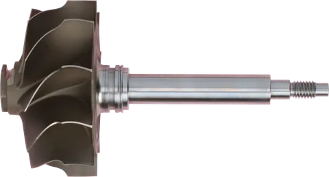
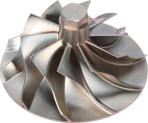
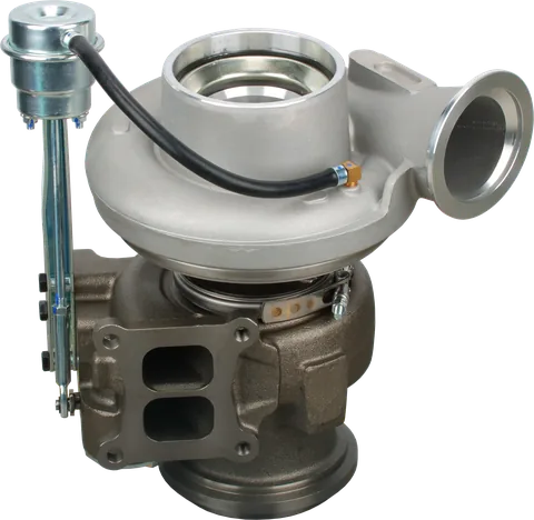
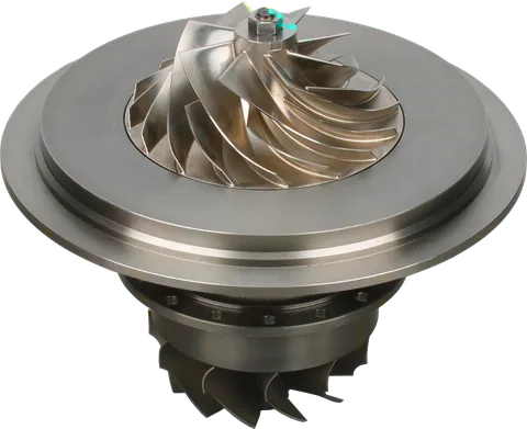
If you have found the shaft moving in and out or noticed a rubbing compressor wheel, the immediate question is whether the rotating assembly is still serviceable. The next question is why it lost clearance control. Replacing damaged parts without checking lubrication, airflow, and boost control can leave the original problem in place.
What the Turbo Thrust Bearing Does
A turbocharger shaft needs support in two directions. Journal bearings control movement across the shaft’s axis, called radial movement. The thrust bearing limits movement along that axis, called axial movement or end play.
Air and exhaust pressure act on different areas of the compressor and turbine wheels. The wheels also experience forces as they redirect flowing gas. Together, these forces create an axial load that the thrust bearing must carry.
This is more complex than subtracting boost pressure from exhaust pressure. Wheel geometry, pressure distribution, airflow, and the turbo’s operating point all matter. The resulting thrust can change in magnitude and can reverse direction as operating conditions change.
The bearing therefore needs to control the rotor during acceleration, steady load, and deceleration. A healthy assembly maintains enough clearance for lubrication while keeping the wheels away from stationary surfaces.
How a Tapered-Land Thrust Bearing Works
Many journal-bearing turbochargers use a fixed-geometry thrust bearing with small, shallow ramps on its working surfaces. These are often described as tapered lands.
A collar attached to the rotating assembly moves past those stationary surfaces. Its motion draws oil into a narrowing gap, building pressure within the oil film. That pressure supports the axial load and separates the metal surfaces.
The engine supplies fresh oil, but the bearing’s supporting film pressure develops locally through rotation and surface geometry. Oil supply pressure alone does not explain its load capacity.
As thrust increases, the working oil film generally becomes thinner under otherwise similar conditions. If oil delivery falls, debris damages the surfaces, or the load becomes excessive, the film may no longer maintain separation. Metal contact then produces heat and wear.
Ball-bearing cartridges handle axial support differently; their inspection and repair requirements should follow their specific design.
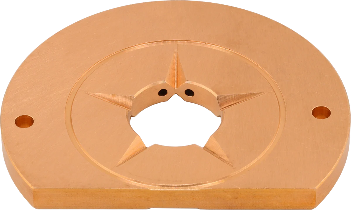
Thrust face: the oil film carries axial load.
Ramped areas: help form the supporting oil film.
Central opening: surrounds the shaft and collar region.
Product photograph from 2026. Numbers identify the features explained below.
What Causes Turbo Thrust Bearing Failure?
When investigating what causes turbocharger thrust bearing failure, remember that several faults can combine. A bearing already damaged by contamination has less margin when boost control problems increase its load.
Oil starvation. A restricted feed pipe, obstructed inlet fitting, low engine oil pressure, or an improperly primed replacement turbo can interrupt lubrication. A normal dashboard indication does not confirm adequate oil delivery at the turbo. Inspect the complete supply path and verify delivery using the applicable service procedure.
Oil contamination. Abrasive particles can score the thrust bearing and collar, damaging the surfaces that support the oil film. Debris may come from engine wear, an earlier turbo failure, or dirty assembly work. Fuel dilution and unsuitable oil can also compromise lubrication. Replacing the bearing without identifying the contamination source leaves the replacement exposed.
High exhaust backpressure. An exhaust restriction or a boost-control fault can change turbine-side pressures and the balance of axial forces. A restricted aftertreatment system deserves investigation when supported by fault codes and pressure testing. High backpressure does not produce the same thrust direction or increase on every turbo; its effect depends on the operating point and geometry.
Intake restriction. A plugged air filter or collapsing inlet hose lowers pressure at the compressor inlet. For the same outlet pressure, the compressor then operates at a higher pressure ratio. This changes its operating conditions and can increase the speed or loading required to meet the engine’s demand.
Excessive boost or overspeed. Incorrect calibration, a sticking wastegate, or malfunctioning variable geometry can move the turbo beyond its intended operating range. Excessive boost and excessive shaft speed are related but are not interchangeable. An acceptable boost reading does not rule out overspeed, particularly when inlet restrictions or charge-air leaks affect operation.
Compressor surge. Unstable compressor flow produces fluctuating pressure and thrust. Repeated surge can stress the thrust assembly, although a flutter sound alone does not establish the cause of bearing damage. See Compressor Surge vs. Turbo Flutter Explained.
Coking after hot shutdown. After sustained heavy operation, heat can soak from the turbine into the center housing after shutdown. Oil exposed to excessive heat can form deposits that restrict passages or impair drainage. Follow the vehicle manufacturer’s cooling and shutdown guidance; there is no universal idle time for every application.
Incorrect assembly also matters. Mismatched collars, obstructed oil passages, or incorrect clearances can undermine an otherwise sound rebuild.
Turbocharger Thrust Bearing Failure Symptoms
Excessive turbo axial play is a strong reason to inspect the thrust assembly. It is not a complete diagnosis on its own.
| Finding | What it may indicate | What to check next |
|---|---|---|
| Axial movement beyond specification | Worn thrust bearing, collar, or another axial locating component | Measure end play and inspect the complete thrust assembly |
| Compressor wheel contact with the cover or backplate | Loss of clearance from axial movement, radial movement, or damaged components | Map contact marks and measure both directions of movement |
| Oil in the compressor or turbine housing | Bearing damage or a separate drainage or pressure problem | Check the oil drain, crankcase ventilation, and sealing areas |
| Scraping, rough rotation, or damaged blades | Active contact or secondary rotor damage | Stop operation and inspect the rotating assembly |
| Scored or heat-damaged thrust surfaces | Lubrication distress or excessive loading | Investigate oil delivery, contamination, and operating conditions |
A wheel touching the cover is not automatically proof of turbo thrust bearing failure. Radial bearing wear can also cause contact. Likewise, smoke and oil leakage are not specific to thrust wear.
Turbo sealing depends on clearances, oil drainage, and pressure conditions. A restricted drain or excessive crankcase pressure can cause leakage without a failed thrust bearing. The turbocharger oil leak guide explains those checks.
How to Diagnose Turbocharger Thrust Bearing Failure Before Ordering Parts
Inspect with the engine stopped and the turbo cool. If the wheel contacts its housing or measured end play exceeds specification, avoid further operation.
-
Identify the exact turbo. Record its part number and any modifications. Obtain the correct clearance limits and measurement instructions. Similar-looking turbochargers can have different requirements.
-
Record the failure circumstances. Note whether symptoms followed installation, an oil-service issue, heavy towing, boost changes, or recurring control faults. Save diagnostic codes and existing operating data before clearing anything.
-
Inspect the inlet and visible wheel surfaces. Look for damaged blades, foreign-object impact, oil accumulation, and contact marks. Do not force the shaft through a tight spot or spin it with compressed air.
-
Measure axial movement correctly. Use a dial indicator with a rigid mounting arrangement and the specified contact point. Apply gentle axial movement according to the service procedure. Avoid pulling against blade tips or introducing sideways movement.
-
Check radial clearance separately. Some journal-bearing turbos have noticeable radial movement while stopped because the operating oil films are absent. That does not make axial movement acceptable by comparison. Each measurement needs its own specification when comparing turbocharger thrust bearing failure vs radial wear.
-
Verify oil supply and drainage. Inspect feed lines, fittings, screens where fitted, and gasket alignment. Check for drain restrictions and excessive crankcase pressure. A feed line that looks clear externally may still contain deposits.
-
Check the oil and filter for evidence. Look for contamination and investigate its source. During disassembly, preserve failed parts and document scoring or deposits before cleaning them.
-
Inspect the air and exhaust paths. Check the filter, inlet hoses, charge-air system, and relevant exhaust restrictions. Test suspect components rather than assuming a fault code identifies the failed part.
-
Verify boost control. Check commanded versus actual boost and the appropriate wastegate or variable-geometry functions using the manufacturer’s procedure. Do not run a mechanically damaged turbo to collect additional driving data.
Wear patterns help establish what happened, but they rarely prove the entire sequence. Wheel contact can create debris that damages bearings, while bearing damage can allow wheel contact. Use the failed turbocharger diagnosis guide to keep the investigation broader than one component.
Repair Kit or Replacement CHRA?
A repair kit makes sense when disassembly and measurement confirm that the reusable components remain within specification. The shaft, thrust collar, bearing housing, sealing areas, wheels, and mating surfaces all need inspection.
A kit cannot restore a worn housing bore, repair a damaged shaft, or make a rubbed compressor wheel serviceable. New thrust parts also cannot correct an unresolved oil supply or boost-control problem.
Choose a kit only when the rebuilder has the correct parts, measurement equipment, assembly specifications, and balancing capability. Consult how to choose a turbocharger repair kit before selecting components.
A replacement CHRA—center housing rotating assembly—is often the more practical option when internal wear or wheel damage makes a kit rebuild unsuitable. It replaces the bearing housing and rotating assembly as a matched unit, but the retained compressor and turbine housings still require inspection.
If those housings, the variable-geometry mechanism, or other external components are damaged, compare a complete turbocharger with the CHRA route. The CHRA vs. complete turbocharger guide covers that decision.
Neither route removes the need to correct the original cause.
Preventing a Repeat Failure
Preventing repeat diesel turbocharger thrust bearing failure starts before installation: resolve oil delivery faults, remove contamination through the specified service process, and repair confirmed intake, exhaust, or boost-control problems. Inspect downstream charge-air components for oil and debris if the old turbo suffered contact or wheel damage.
Use the specified engine oil and filter, follow the turbo supplier’s priming procedure, and confirm correct line routing and unobstructed drainage. Follow application-specific requirements for actuator setup or calibration.
After installation, verify oil pressure, leakage, and boost operation using the approved procedure. Keep the replacement turbocharger installation checklist with the job.
Common Questions
How much turbo axial play is normal?
Use the specification for the exact turbocharger and its stated measurement procedure. A small designed clearance can exist, but there is no universal acceptable number. Hand feel alone cannot establish whether the thrust assembly is serviceable.
Does a rubbing compressor wheel prove thrust bearing failure?
No. Excessive axial movement can cause contact, but radial bearing wear, shaft damage, foreign objects, or housing problems can also cause rubbing. Check axial and radial clearance separately and inspect the contact location.
Can I drive with excessive turbo end play?
Avoid running the engine when end play exceeds specification or the wheel contacts its housing. Continued operation can worsen wheel damage and oil leakage. Arrange inspection before further driving.
Will a new thrust bearing stop a turbo oil leak?
Only if thrust assembly damage caused the leakage and the remaining components are serviceable. Restricted oil drainage, excessive crankcase pressure, and other faults can cause leakage even when the thrust bearing is healthy.
Is a 360-degree thrust bearing always an upgrade?
No. Circumferential coverage alone does not establish load capacity or compatibility. Oil supply, working surface geometry, materials, and the matching collar matter. Use a validated assembly for the specific turbo and operating conditions.
Can I install a repair kit without balancing?
Do not assume the original balance remains acceptable after disassembly. Follow the turbo rebuilder's balancing requirements, including assembled CHRA verification where specified. Alignment marks are not a substitute for appropriate balancing equipment.
Can turbocharger thrust bearing failure be repaired?
A repair kit may be suitable if reusable components remain within specification. Internal wear or wheel damage may favour a replacement CHRA. Correct the original cause.
For help selecting replacement parts after turbo thrust bearing failure, contact LeadTurbo with your turbo part number, vehicle details, symptoms, and any measured end play.