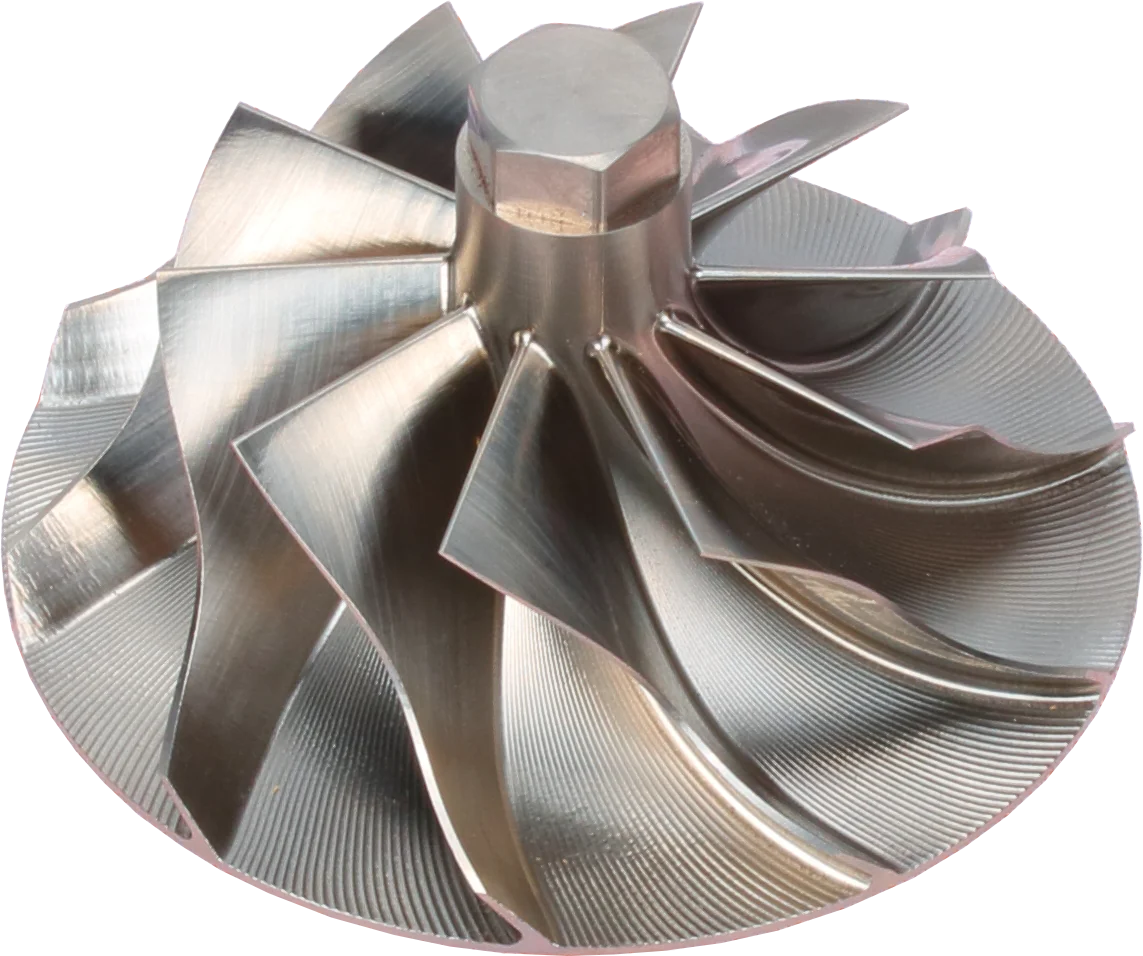
Take a turbocharger with a suspected cracked wheel out of service. A small crack can grow until a blade separates or the hub breaks apart. For shops investigating compressor wheel failure, the useful questions are where the damage started, how it progressed, and what operating condition will still be present when the replacement goes in.
What causes turbocharger compressor wheel cracking?
Compressor wheel fatigue includes two different loading patterns. Low-cycle fatigue develops as wheel speed repeatedly rises and falls, changing centrifugal loading through the hub. The central bore, bore ends and transitions into the hub back face can concentrate stress. Repeated acceleration from light load to heavy work can gradually grow a crack there. A load cycle is a substantial change in stress; it is not one revolution of the wheel.
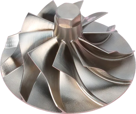
High-cycle fatigue comes from repeated blade flexing. Airflow disturbances can excite a blade's natural vibration, sometimes strongly at particular operating speeds. Blade roots, fillets and sections near splitter leading edges deserve attention. Splitters are the shorter blades between full blades. This damage can develop while engine load looks steady; the blade and supporting disk vibrate as a connected structure.
Impact or foreign object damage (FOD) usually begins with a strike: a dent, gouge, bent leading edge or missing piece. An impact notch can also start a fatigue crack, so the two mechanisms can overlap.
Turbocharger compressor wheel fatigue vs impact damage: read the fracture
Fracture appearance is evidence, not a verdict. Fatigue may leave a relatively smooth growth area with curved beach marks, followed by a rougher final separation. Those bands are not always visible, especially on small blades or surfaces battered by loose fragments.
| Suspected failure mode | Likely starting area | Useful evidence | Important limit |
|---|---|---|---|
| Low-cycle hub fatigue | Bore wall, bore end or hub back face | Crack extending through the hub; progressive growth beside a rough final break | Confirm the origin before blaming ordinary service hours |
| High-cycle blade fatigue | Blade root, fillet or splitter region | Localized fracture with a small growth area, sometimes without obvious inlet dents | A smooth-looking break alone does not prove resonance |
| Impact/FOD | Exposed blade leading edge | Denting, folded metal, embedded debris or neighboring impact marks | Later impacts can obscure an earlier fatigue origin |
| Rapid final overload | Hub or remaining blade section | Large rough fracture and extensive secondary damage | A burst may finish an old fatigue crack; it does not prove a single overspeed event |
Find the oldest fracture origin, not simply the largest damaged area. If the hub, blades and housing have struck each other, a specialist may need microscopy to separate the initial break from the damage that followed.
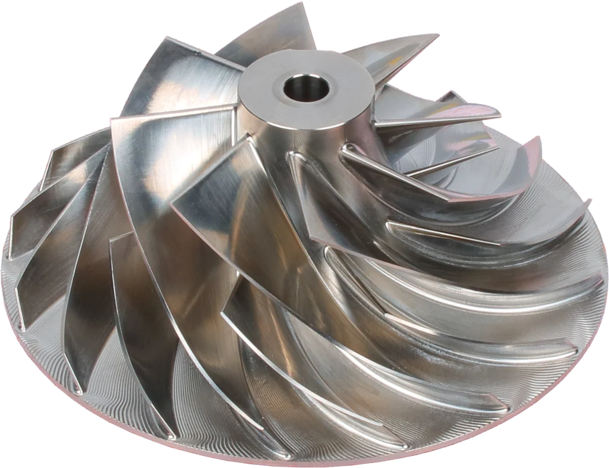
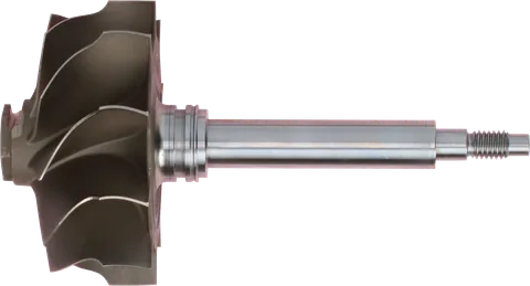
Blades: inspect for chips, bends and contact marks.
Hub: part of the balanced rotating assembly.
Outer blade tips: check for housing rub.
Product photograph from 2026. Numbers identify the features explained below.
Why demanding duty speeds up the damage
Diesel turbocharger compressor wheel fatigue depends on the duty pattern. A delivery truck or transit bus repeatedly moving from idle to boost gives the hub a different stress history than a generator carrying a stable load. Loader bucket cycles and repeated grade changes matter too. Hours alone do not describe accumulated fatigue exposure.
High boost usually demands more compressor work, but manifold boost is not a wheel-speed measurement. Compressor pressure ratio uses absolute outlet and inlet pressures. At altitude, lower inlet pressure means that maintaining the same outlet pressure requires a higher ratio and can require higher shaft speed. Rotational stress rises sharply as shaft speed increases. Follow the engine's altitude limits and derating strategy.
Elevated compressor discharge temperature can accompany high pressure ratio or inefficient operation. Higher wheel metal temperature reduces the strength available from an aluminum alloy. Air temperature is not identical to metal temperature, and a sensor after the charge-air cooler cannot establish how hot the wheel became.
A charge-air leak may leave manifold boost low while a boost controller asks for more turbocharger output. Depending on the control strategy, speed can climb. Aggressive tuning, incorrect boost-control settings or an inlet restriction can also consume speed margin. Diagnose these conditions before increasing boost to compensate.
Normal stop-start work should be covered by the approved turbo's duty rating. Where the job allows, reduce unnecessary rapid load swings and correct control hunting. Recurring breaks on the same route call for an application review using recorded operating conditions.
Design and material still matter
A cast aluminum wheel can be a suitable, durable original-equipment design. Casting quality matters because pores or inclusions can become fatigue origins. Alloy, heat treatment, surface finish and hub geometry all affect the result.
A properly specified forged wheel can offer fatigue advantages, but a marketing label cannot establish its operating limit. “Billet” identifies machining stock rather than a complete material or durability specification. A different blade shape also changes vibration behavior, even when the outside diameter matches.
Boreless hubs remove the central through-bore and its associated stress concentration. They still have attachment features, blade roots and other possible crack origins. Use the wheel, shaft and housing combination approved for the application; a boreless design is not a field conversion.
How to check turbocharger wheels for cracks and preserve the evidence
Investigate compressor wheel cracking with the turbocharger out of service. Photograph the damage before cleaning, and keep fracture pieces protected from rubbing together. A fracture surface needed for analysis should not be wire-brushed, ground or blasted.
- Record turbocharger and engine identification, calibration, operating hours and the actual duty pattern.
- Save fault codes and available logs for boost, barometric pressure, temperatures and shaft speed.
- Note recent tuning, intake repairs, wheel replacement, balancing work and symptoms before failure.
- Check for leaks, inlet restrictions and evidence of housing contact without spinning the damaged assembly.
| Inspection area | What to check |
|---|---|
| Bore and bore ends | Look for radial cracks, scoring, fretting and tool damage |
| Hub back face | Inspect transitions and fillets; record cracking or rub tracks |
| Blade roots and splitter leading edges | Examine both blade faces under magnification for fine cracks, dents and local deformation |
| Nut seat and mating hardware | Check dents, burrs, fretting or uneven contact that could affect seating and clamping |
On a dismantled wheel, a qualified rebuilder can use a dye penetrant procedure suitable for aluminum, paying particular attention to the bore and blade roots. The surface must be correctly cleaned and prepared. Penetrant reveals cracks open to the surface; it cannot rule out internal defects or certify remaining fatigue life.
Disassembly and nut installation must follow the exact turbocharger procedure. Do not polish away seat damage and assume the assembly is acceptable.
Compare repeated failures by exact part number and crack location. Similar breaks across several units justify checking shared calibrations, operating conditions and replacement specifications. Keep manufacturing defects among the possibilities until the evidence narrows them.
A burst requires more than a replacement wheel
A compressor wheel burst releases fragments with enough energy to make housing integrity a containment issue. The housing is part of a validated assembly, not a guarantee that every fragment will remain inside. Wheel substitutions or housing modifications can change that relationship.
Debris can also travel into the outlet piping, charge-air cooler and intake manifold. Remove and inspect the affected intake path before fitting a replacement. Clean or replace components according to OEM instructions; a cooler that traps fragments may need replacement.
If debris may have entered cylinders, follow the engine manufacturer's inspection procedure before cranking. Installing a new turbocharger does not remove that debris.
Prevent the next failure
Use the failure evidence to choose corrective work. Replacing the turbo without changing an abusive operating condition leaves the next wheel exposed to the same stress.
| Duty or finding | Prevention priority | What to verify |
|---|---|---|
| Frequent heavy load cycles | Confirm the turbo specification covers the actual duty; correct control hunting | Review load and boost trends over a representative shift |
| High boost or altered calibration | Restore an approved calibration and verify correct turbo fitment | Check loaded operation against the approved limits |
| High-altitude operation | Preserve OEM altitude compensation and required derating | Review barometric pressure and available shaft-speed data |
| Hot compressor discharge | Evaluate inlet temperature, pressure ratio and operation outside the intended range | Use suitable temperature data; do not infer wheel temperature from cooled manifold air |
| Leaks or inlet restriction | Repair leaks and service the inlet system to OEM requirements | Recheck restrictions and commanded versus actual boost under load |
| Impact or assembly damage | Correct the entry path for debris and replace damaged seating components | Inspect ducting, filter sealing and assembly condition |
| Uncertain replacement specification | Confirm wheel, shaft, housing and calibration compatibility before assembly | Match the complete turbo identification and engine application |
There is no universal retirement interval for every aluminum wheel. Use application-specific service instructions and investigate repeat failures by part number, crack origin and duty history.
Parts for this guide
 169413 S4DC028 Turbocharger Compressor Wheel for CAT 3516
169413
Compressor wheel
In Stock
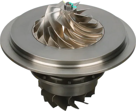
 VE110069 Turbocharger Core for Suzuki Isuzu 4TNA (VZ21)
FOR VE110069
Core
On backorder — orders accepted
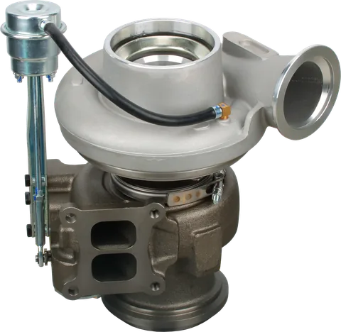
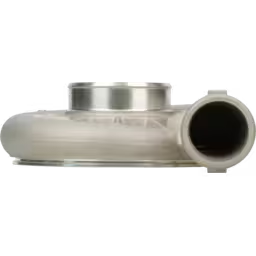 4045417 HE800FG HX82 Compressor Housing for Cummins QSK45
4045417
Compressor Housing
In Stock
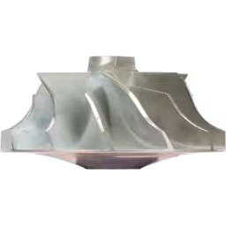 410349-0004 CW Compressor Wheel TV9101 Turbocharger
410349-0004 CW
Compressor wheel
In Stock
Common Questions
Does every fatigue fracture show beach marks?
No. Small growth areas or secondary damage may hide them. Combine crack location, fracture examination and operating history; a ragged final break does not exclude fatigue.
Can a wheel crack without an overspeed fault?
Yes. Repeated speed cycles, blade vibration or existing damage can cause turbocharger compressor wheel cracks without overspeed being recorded. Missing shaft-speed data also limits what fault records prove.
Does a forged wheel eliminate fatigue?
No. Alloy, processing, geometry, temperature and loading still control durability. A forged or machined wheel does not automatically permit more boost.
Why can the same boost setting be harder on a turbo at altitude?
Lower inlet pressure raises the pressure ratio needed for the same outlet pressure. Shaft speed and discharge temperature can rise. Follow OEM altitude limits and derating.
Is a new CHRA enough after a burst?
Only after checking housings, clearing the intake path and correcting the cause. Trapped cooler debris or possible cylinder ingestion can require additional replacement and engine inspection.
Can compressor wheel cracking be repaired?
Replace a cracked wheel. Welding or grinding cannot restore qualified fatigue life. Have the assembly assessed, then use the correct replacement parts and balancing process.
Does compressor wheel failure require turbocharger replacement?
Have the assembly assessed before choosing replacement parts. Replace a cracked wheel and check housing integrity after a burst.
For help identifying a replacement turbocharger or CHRA, contact LeadTurbo with the turbo part number, engine details and operating conditions.