When comparing replacement cores or rebuild quotes, “balanced” is an incomplete description. It could mean the compressor wheel was checked separately, the turbine shaft assembly received two-plane balancing, or the finished center housing rotating assembly—CHRA—was tested and corrected at high speed.
Those operations answer different questions. Understanding low-speed vs high-speed turbocharger balancing helps explain the extra cost of VSR turbo balancing and gives buyers something more useful to evaluate than a sticker.
First, identify what needs correcting
Unbalance describes how the rotating mass is distributed relative to its rotation axis. A part can look concentric and still have an uneven mass distribution inside it. Conversely, machining away enough material to achieve a balance reading does not necessarily make a distorted part serviceable.
Three terms describe the problem.
Static unbalance means the center of mass sits off the rotation axis. Think of a wheel with extra mass concentrated toward one side. On ideal, nearly frictionless supports, that heavy side would tend to settle downward.
In a turbocharger, manufacturing tolerances, uneven material density, or an off-center wheel bore can produce this condition. On a welded turbine wheel and shaft, an offset at the joint can also move the mass away from the intended axis.
Couple unbalance means different axial portions of the rotor create opposing forces that tend to rock it. Picture a heavy spot toward one end and another on the opposite side toward the other end. Their combined center of mass can remain on the axis, so a gravity check may reveal nothing.
Angular misalignment between a turbine wheel and shaft can contribute to couple unbalance. The problem concerns both the amount of uneven mass and its position along the rotor.
Dynamic unbalance generally combines static and couple effects. Most real components do not fit neatly into only one category. They can push sideways and rock as they rotate.
Service damage changes the picture further:
- Uneven erosion removes mass from particular areas of a wheel.
- Nonuniform deposits add mass.
- Overspeed can permanently deform a wheel.
- Overtemperature can distort components and change their alignment.
These conditions require inspection before balancing. A favorable machine reading cannot establish that an overheated, cracked, or deformed wheel is safe to reuse.
How does low-speed turbocharger balancing work?
At a suitable low balancing speed, a serviceable turbocharger rotor component can be treated approximately as rigid: bending has little effect on the measurement.
The machine measures the rotating response and determines corrections at two axially separated locations, called correction planes. Two-plane balancing addresses both the sideways force associated with static unbalance and the rocking effect associated with couple unbalance.
For a turbine shaft-wheel assembly, the planes are approved correction areas on the component. For a compressor wheel, they may be designated areas toward its front and back. Their exact locations depend on the design and balancing procedure.
The operator removes controlled amounts of material at calculated angular positions and radii, then measures again. Removing material in two correction planes provides control over both force and moment. Grinding a single convenient spot does not offer the same control.
The mounting arrangement matters just as much as the cutting:
- The shaft’s locating surfaces must be clean and undamaged.
- A compressor wheel must sit correctly on its balancing arbor.
- The arbor and fixture must be calibrated or compensated appropriately.
- Repeated measurements must be consistent enough to support a reliable correction.
Otherwise, the machine may partly measure the tooling or a mounting error, and the operator may “correct” the wheel for a problem that disappears when it is installed.
This is why static vs couple unbalance is more than terminology. A wheel that passes a simple heavy-side check can still need substantial two-plane correction.
Why the assembled core needs VSR turbo balancing
Separately balanced parts do not guarantee a balanced assembly.
The compressor wheel, turbine shaft, thrust components, spacers where fitted, and retaining hardware form a stack. Small errors in seating, concentricity, and component alignment combine during assembly. Each part also retains some residual unbalance.
At high speed, the shaft’s flexibility becomes relevant. Its response depends on how mass is distributed along it and how the bearings support it. Passing through a resonance can amplify vibration that looked modest at low speed.
Centrifugal growth and operating temperature can also alter dimensions and contact conditions at fits. That does not mean components should become loose; it means their running geometry is not perfectly identical to their stationary geometry.
VSR testing evaluates the assembled core under controlled high-speed conditions. Typically, compressed air drives the turbine while a regulated oil supply supports the bearings. Sensors record vibration as the rotor passes through the prescribed speed range.
The operator then makes permitted trim corrections and repeats the run. Depending on the design and equipment, correction areas may include designated compressor-side nut or hub surfaces. The number and location of usable planes are procedure-specific.
A cold, air-driven test does not reproduce every temperature and load found on an engine. It does, however, reveal assembled behavior that individual component balancing cannot establish.
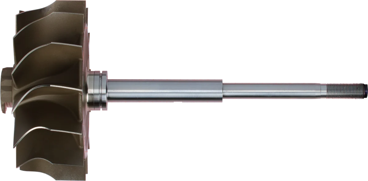
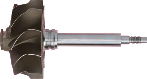
Turbine wheel: exhaust energy drives the shaft.
Shaft surface: inspect wear and scoring before reuse.
Shaft end: connects to the compressor-side rotating parts.
Product photograph from 2026. Numbers identify the features explained below.
Modal balancing and influence-coefficient balancing
High-speed balancing needs a way to connect measured vibration with useful corrections. Modal balancing and influence-coefficient balancing approach that task differently.
| Approach | Main question | Information it uses | Practical limitation |
|---|---|---|---|
| Modal balancing | Which bending behavior is being excited, and how can its excitation be reduced? | Rotor mode shapes, resonance behavior, and suitable correction locations | Requires knowledge of the rotor’s modes and enough effective correction locations |
| Influence-coefficient balancing | How does a known correction change the measured vibration? | Measured or calibrated relationships between corrections and vibration responses | Depends on representative calibration, repeatable mounting, and stable test conditions |
Modal balancing works from the rotor’s bending behavior. A flexible shaft can vibrate in different shapes, called modes. A correction that strongly affects one mode may have little effect on another.
The balancing strategy selects corrections that reduce excitation of the relevant modes while preserving acceptable behavior elsewhere. This requires understanding where the rotor bends and which correction locations can influence that motion. The limited accessible correction areas on a small turbocharger can make that difficult.
Influence coefficient balancing works from measured cause and effect. A known trial change establishes how a correction at one location affects vibration at selected measuring locations and speeds. Suitable machine calibration can supply these relationships without repeating every trial on every core.
The response includes amplitude—how much vibration occurs—and phase, its timing relative to a rotational reference. Together, they help determine where and how much correction is needed.
A correction in one plane can affect multiple measurements. The calculation therefore considers those interactions rather than treating each plane independently.
Influence coefficients are not universal or independent of speed. Bearing behavior, fixtures, rotor design, and operating conditions affect them. Using responses across several speeds helps avoid a correction that improves one point while worsening another.
The approaches can also overlap. Knowledge of rotor modes can inform a measurement-based balancing procedure. Buyers should focus on the validated process and final result rather than expecting one algorithm name to guarantee quality.
Reading a turbocharger VSR balance report: vibration is not the same as unbalance
A low-speed machine may report residual unbalance. A high-speed turbo core balancing machine may display vibration amplitude against shaft speed. Those are related measurements, but they are not interchangeable.
The recorded vibration depends on the rotor, bearings, housing, fixture, sensor position, and test conditions. Comparing two charts requires knowing their units, measurement method, and applicable limits.
Unbalance primarily excites vibration once per shaft revolution, often called the synchronous or 1× response. A useful procedure evaluates this response through the required speed range, including significant peaks.
When diagnosing turbocharger vibration after VSR balancing, remember that not every vibration peak comes from unbalance. Oil-film instability can generate subsynchronous motion, below shaft rotational frequency. Rubbing and other mechanical problems can also complicate the signal. Repeatedly removing material will not reliably fix those conditions.
A credible result identifies what was measured and whether the core met the correct acceptance criteria. A smooth-looking trace without speed labels, units, or traceability provides limited evidence.
What a good rebuild shop does—and why it costs more
A sound rebuild starts with dimensional and condition checks. Balancing comes after deciding which parts are suitable for service.
A careful shop should be able to explain its process for diesel turbocharger VSR balancing:
- Inspect wheels and shaft for damage, distortion, runout, and unacceptable wear.
- Check bearing locations, thrust surfaces, and component fits against applicable specifications.
- Balance reusable or replacement rotating components using the appropriate procedure.
- Assemble clean parts with the specified retention method.
- Test the finished core using suitable tooling, lubrication conditions, and speed range.
- Make corrections only within permitted areas and material-removal limits.
- Repeat the test and retain a result traceable to the core or job.
The extra cost covers equipment, fixtures, maintenance, calibration, oil-system control, skilled labor, and repeated test runs. It also covers recognizing when an unstable result calls for inspection or reassembly instead of another correction cut.
A shop can outsource high-speed balancing competently. What matters is whether the completed core receives the required work and whether the result follows that particular unit.
Red flags in cheap rebuilds
Low price alone does not establish poor workmanship. Vague process claims deserve closer attention.
Watch for:
- “Factory-balanced wheels” offered as the entire explanation for assembled balance.
- Paint marks presented as proof that reassembly needs no verification.
- The same generic balance graph supplied with unrelated cores.
- A claimed pass without an identifiable test procedure or acceptance limit.
- Aggressive grinding outside approved correction areas.
- A promise that balancing will cure every whistle, oil leak, or bearing problem.
Index marks can help preserve component orientation, but they cannot confirm repeatable seating or account for replaced parts. Likewise, a machine photograph proves little about the work performed on a particular CHRA.
Common Questions
Does VSR balancing replace low-speed balancing?
No. Component balancing removes the underlying unbalance before assembly. High-speed balancing then addresses the assembled core’s response. Using final trim corrections to compensate for poorly balanced or defective components can leave problems unresolved.
Can individually balanced parts make an unbalanced CHRA?
Yes. Small differences in mounting fits, seating surfaces, component alignment, and assembly can shift the combined mass distribution. The finished rotating assembly needs verification even when its individual parts have passed balancing.
Does every turbo need the same VSR test speed?
No. The appropriate speed range and acceptance limits depend on the turbo design and validated test procedure. A higher advertised test speed does not automatically mean a better balance job.
Is a VSR graph proof that a turbo is good?
It is evidence of vibration performance under the recorded test conditions. It does not independently prove correct clearances, sound materials, actuator calibration, or performance under exhaust heat and engine load.
Should a CHRA be checked again after changing the compressor wheel?
Yes. Replacing the wheel changes the rotating assembly. Disturbing its mounting or retention can also change the balance result. Follow the applicable assembly procedure and have the completed core checked again.
Will VSR turbo balancing eliminate every turbo whistle?
No. Unbalance can produce a speed-related tone, but airflow, leaks, blade interaction, rubbing, and bearing instability can also generate noise. Balancing addresses unbalance; other causes require their own diagnosis.
Does a replacement turbocharger need VSR?
Separately balanced parts do not guarantee a balanced assembly. The finished core needs high-speed verification using the appropriate speed range and acceptance limits for its design and validated test procedure.
Contact LeadTurbo with your turbo part number and symptoms for help identifying a suitable replacement turbo, CHRA, or repair parts.