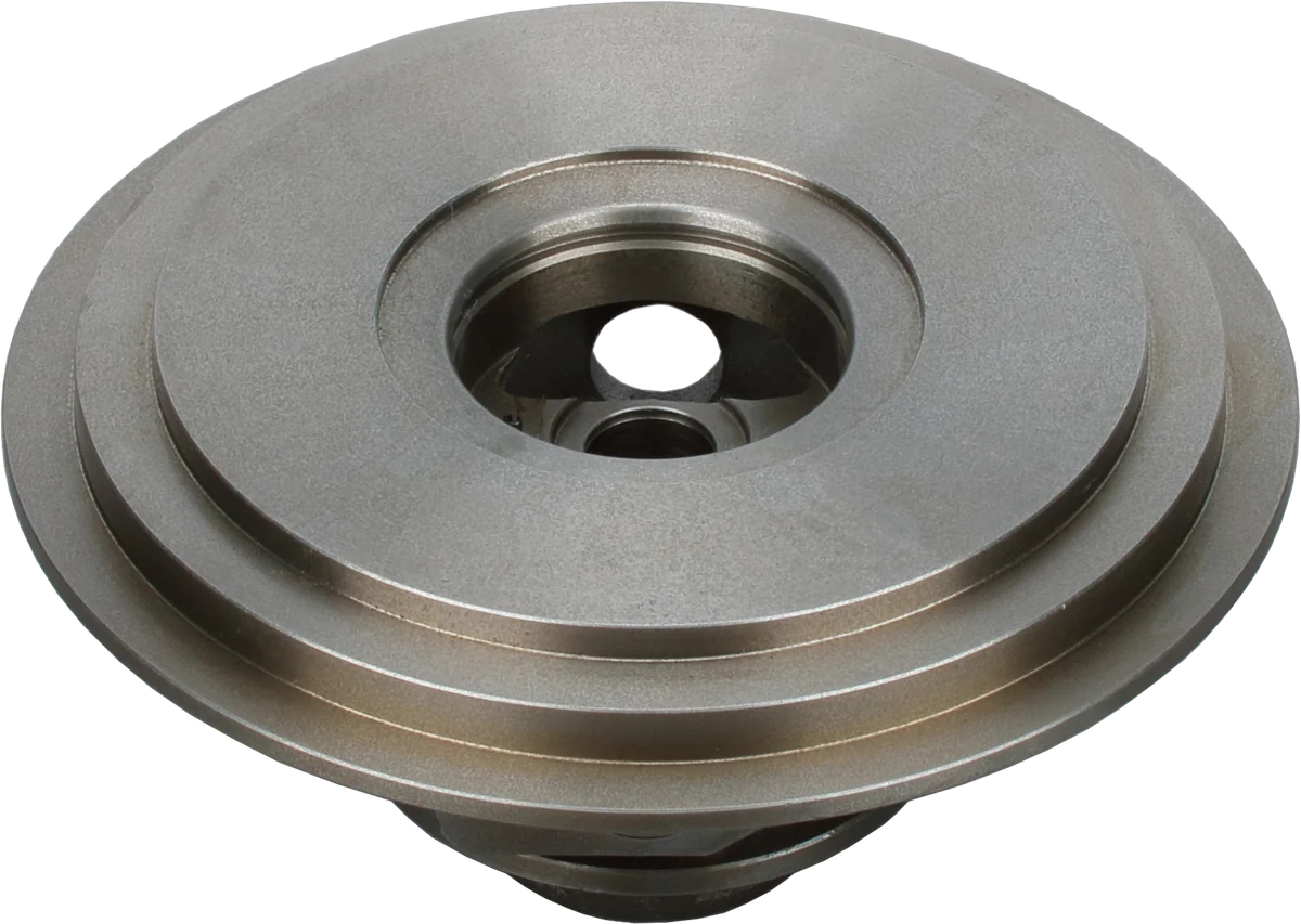
Understanding turbo seals on most diesel turbochargers starts with one distinction: the ring is only part of the system. It limits flow through a narrow path while surrounding hardware keeps bulk oil away. That explains why a replacement ring may be correct yet fail to cure leakage when the working clearances, oil level, or pressures are wrong.
How do turbo seals hold back oil and gas?
A conventional lip seal rubs against a rotating shaft, an arrangement generally unsuitable for the speed and temperature of a diesel turbocharger's main shaft.
A turbo piston ring seal instead uses a split metal ring in a groove on the shaft or a rotating collar. In a common arrangement, spring tension holds the ring against the stationary housing bore while the grooved part rotates inside it. Small running clearances allow that movement.
Those clearances and the ring's end gap form a restricted flow path. Gas loses pressure as it passes through restrictions; pressure differences also affect which groove face the ring bears against. The arrangement provides labyrinth-like flow resistance, although a split ring is not the same construction as a multi-tooth labyrinth seal.
The ring therefore serves two related purposes: limiting air or exhaust entering the bearing cavity and resisting oil moving toward either wheel. It does not create a watertight barrier.
Engine oil supply pressure is not normally applied directly across the ring. Most of that pressure drops through the bearing system before the oil reaches the drain cavity. Comparing dashboard oil pressure with boost pressure misses this distinction.
Turbocharger compressor seals vs turbine seals
Both ends need gas control and oil control, but they do different jobs in different temperatures. Parts described as a turbo oil seal may include a ring, a ring carrier, or static seals; verify what the kit actually contains.
| Feature | Compressor side | Turbine side |
|---|---|---|
| Ring location | Often on a separate rotating sleeve, collar, or flinger | Commonly in a shaft or hub groove near the turbine wheel |
| Oil handling | Slinger and backplate geometry redirect oil from the thrust-bearing area | Shaft shoulders, deflectors, and drain spaces keep oil away from the hot ring |
| Main challenge | Pressure changes around the wheel back and inlet | Hot exhaust, deposits, and thermal movement |
| Design variation | Ring count, collar profile, and backplate bore differ | Ring count, groove dimensions, and heat-shield arrangement differ |
An oil slinger, also called a flinger, spins oil outward by centrifugal action. Surrounding stationary surfaces catch that oil and guide it toward the drain. It reduces the amount of liquid that reaches the ring.
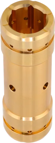
Thrust collar geometry matters because shoulders, grooves, and mating faces help establish these oil paths. Depending on the design, the ring carrier and slinger may be separate pieces or combined. A collar that slides onto the shaft is not necessarily compatible.
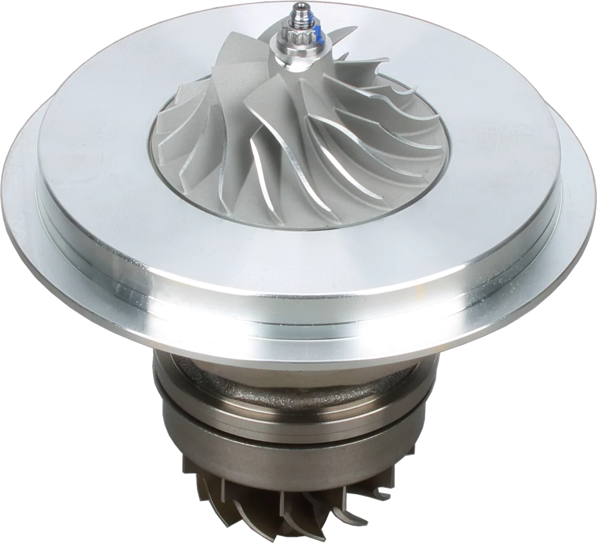
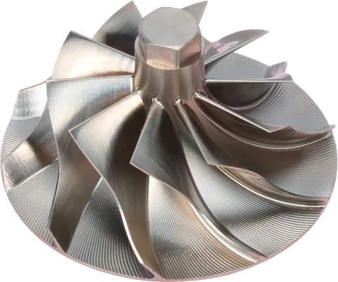
Compressor wheel: transfers shaft power to the air.
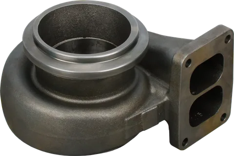
Bearing housing: supports the lubricated rotating assembly.
Turbine wheel: exhaust energy drives the shaft.
Product photograph from 2026. Numbers identify the features explained below.
Pressure balance changes with operating conditions
Pressure at the sealing region matters more than the boost gauge reading. The pressure behind a compressor wheel is influenced by the local airflow and geometry; it is not simply identical to intake manifold pressure.
| Operating condition | What changes | Why sealing becomes harder |
|---|---|---|
| Idle or light load with low boost | Typically less compressor pressure rise and lower rotor speed | Less pressure assistance and weaker centrifugal oil separation |
| High intake restriction | Pressure falls upstream of the compressor | Depending on design, connected seal regions can see a less favorable pressure difference |
| Elevated crankcase pressure | Pressure rises at the drain outlet and can reach the bearing cavity | Less driving force for drainage and oil containment |
| Restricted oil return | Oil leaves the housing too slowly | Oil can accumulate around a ring designed to restrict flow, not hold a flooded sump |
Low boost alone does not mean oil will leak. A healthy turbocharger should operate through its specified idle conditions. An unthrottled diesel also does not automatically develop the strong idle vacuum associated with a throttled gasoline engine.
If local compressor-side pressure drops below bearing-cavity pressure, however, oil available at the seal can be drawn outward. Intake restriction can worsen that imbalance. Meanwhile, a slow drain or crankcase pressure can increase the amount of oil waiting at the ring. These effects can combine without a broken ring.
Most installations return aerated oil by gravity. The drain must carry oil and displaced gas, so its effective flow capacity matters, not just whether a wire fits through it.
What the turbo heat shield protects
The turbine can transfer heat into the center housing through radiation and conduction. An internal shield and designed air spaces reduce that transfer near the wheel back and bearing housing. They do not eliminate heat conducted through the shaft and other metal connections.
This shield is distinct from an external turbine blanket. Its shape, location, and clearance are part of the turbocharger assembly; it should not be omitted because the turbo still bolts together without it.
Excess heat can turn residual oil into deposits around the turbine-end groove and drain spaces. Deposits can impair ring movement or oil drainage. Thermal distortion and changes in running clearance can further weaken sealing.
Where fitted, center-housing water cooling provides another way to manage heat. During rebuilding, preserve the specified shield, spacing, and cooling provisions instead of treating heat protection as optional hardware.
Oil has more than one possible escape route
Oil in a compressor housing does not identify the exact leaking interface. During teardown, think in terms of paths:
- Around the compressor ring: Oil can pass through the ring, groove, and bore restrictions into the wheel-back space and then enter the compressor airflow.
- Along internal mating clearances: On some designs, oil can follow shaft-to-sleeve or wheel-bore clearances toward the wheel inlet, bypassing the outer ring's main restriction.
- Toward the turbine wheel: Oil can move beyond the oil-control features and turbine ring into the hot gas path.
- Across a static joint: A damaged backplate O-ring or another stationary seal can leak independently of the shaft sealing arrangement.
These routes explain why installing a new ring cannot compensate for a worn bore, damaged mating face, or incorrect sleeve.
How factory oil-leak testing simulates service
A meaningful oil-leak test recreates conditions that affect the entire sealing system. Depending on the manufacturer and test purpose, this may use an engine or a dedicated fixture that rotates the assembly and establishes controlled oil and gas conditions.
Factory procedures vary; a development validation test is not necessarily the production check performed on every unit.
| Controlled factor | What the test evaluates |
|---|---|
| Oil temperature and supply | Leakage with defined viscosity, flow, and pressure |
| Rotor speed and gas pressures | Seal behavior under specified running conditions |
| Inlet restriction or low-load operation | Sensitivity to an unfavorable compressor-side pressure balance |
| Drain arrangement and outlet pressure | Whether oil removal matches the intended installation conditions |
| Test duration and inspection method | Repeatable evidence of oil reaching either gas path |
Technicians inspect specified areas or collect and measure carryover, then compare results with the applicable acceptance criteria.
Because turbo seals depend on rotation, drainage, and pressure balance, pouring oil into a stationary cartridge is not an equivalent test. A successful high-speed balance run alone also does not establish leak performance across all operating conditions.
Diesel turbocharger seal replacement: preserving the sealing system
A kit supplies parts; it does not restore worn sealing surfaces. Use the service information for the exact turbocharger assembly, including its revision, to establish measurements and installation requirements.
- Measure the turbocharger seal ring end gap correctly. Check the installed end gap in the specified bore, plus groove clearance and bore condition. A free ring's visible opening is not its installed gap. An undersized gap can close with heat; an excessive gap enlarges a leakage path. Do not borrow limits from another turbo family.
- Follow the specified orientation. Some rings have directional features; others do not. Follow instructions for ring faces, end-gap position, and multiple-ring arrangements. There is no universal clock position that applies to every design.
- Protect the ring during installation. Use the specified method to avoid excessive stretching, twisting, or catching an end on a bore edge. Confirm that it is seated properly.
- Preserve the geometry. Inspect groove flanks, carrier surfaces, collar faces, and sealing bores for wear or deposits. Do not widen grooves or polish away material to make assembly easier.
- Keep sealant out. Never put RTV or other sealant on the rings, grooves, or internal oil-control surfaces. Use specified static seals and gaskets; excess sealant can obstruct oil passages.
- Restore the complete assembly. Fit the correct flinger, thrust components, backplate, and heat shield, then complete the required clearance checks and balancing procedures.
Common Questions
Are these rings the same as engine piston rings?
No. They share a split-ring principle, but their dimensions, materials, tension, and working surfaces are specific to the turbocharger. Use the specified replacement ring.
Should the ring spin with the shaft?
In many common designs, the ring stays substantially stationary in the housing bore while the shaft or collar rotates inside it. Follow the design-specific service requirements.
Does an oily compressor prove the ring failed?
No. Oil may arrive through crankcase ventilation or pass through another internal route. The oil's location alone does not isolate a failed ring.
Can I file a replacement ring to fit?
Do not modify a replacement ring unless the manufacturer's procedure explicitly requires it. Gap, tension, and groove clearance work together; a ring that needs alteration may be the wrong part.
Should I replace a damaged heat shield?
Yes. Use the correct replacement and restore the specified spacing. Bending it until it clears may change the thermal barrier or create contact with rotating parts.
Can new turbo seals fix every oil leak?
No. New rings cannot restore a worn bore or correct pressure imbalance, poor drainage, or mismatched internal parts. Repair the affected sealing system and verify its operating conditions.
Why do turbocharger seals leak?
Turbocharger seals can leak when pressure imbalance, poor oil drainage, worn sealing surfaces, or mismatched parts disrupt oil control. The ring is only part of the sealing system, so leakage can occur without a broken ring. Check the oil return, crankcase pressure, sealing bores, and internal parts before assuming the ring has failed.
Can turbocharger seals be replaced?
Yes. Turbocharger seal rings can be replaced using the specified parts and service instructions for the exact assembly. Check the installed ring end gap, groove clearance, and bore condition, and complete the required clearance checks and balancing procedures. New rings cannot restore worn sealing surfaces or correct poor drainage or pressure imbalance.
For help matching seal components or a repair kit, contact LeadTurbo with the turbocharger part number and engine details.