A useful answer to “how does a turbo compressor work?” explains why a wheel that fits inside a cover can still be the wrong replacement. Most diesel turbochargers use a centrifugal compressor with a rotating wheel and stationary passages designed together. Their shape, surface condition, and clearances determine how effectively shaft power becomes intake pressure.
For a mechanic replacing a housing, wheel, or center housing rotating assembly (CHRA), that connection matters: restoring the original airflow path is part of restoring performance.
How does a turbocharger compressor build pressure?
Exhaust energy drives the turbine, which turns the compressor through a shared shaft. On the cold side, filtered air normally enters near the center of the wheel, traveling roughly along that shaft. The wheel turns the flow outward before the stationary passages collect and deliver it.
| Stage | What happens to the air | Practical purpose |
|---|---|---|
| Inlet and inducer | Air approaches along the shaft and enters the curved blade passages | Guides airflow into the rotating wheel |
| Impeller to exducer | Rotating blades drive air outward and give it swirl | Adds energy, raising velocity, pressure, and temperature |
| Diffuser | Air crosses an annular passage outside the wheel | Slows airflow to recover static pressure |
| Volute and outlet | The scroll collects air around the diffuser and directs it toward the outlet | Delivers the combined flow, with potential for further pressure recovery |
Only the wheel transfers shaft power into the air. It increases the air's energy, producing both higher velocity and a pressure rise inside the impeller. Compression also raises temperature.
In the diffuser and volute, controlled slowing converts some of the outgoing air's velocity into static pressure: the pressure exerted locally on the passage walls. These stationary parts add no shaft energy. Friction, turbulence, and separated flow reduce how much useful pressure survives to the outlet.
The compressor does not deliver one fixed boost pressure just because the wheel reaches a particular speed. Pressure rise depends on airflow, inlet conditions, and the resistance of the connected system. That is why a wheel and housing combination must be evaluated as a complete compressor.
Turbocharger compressor inducer vs exducer: dimensions and blades
The compressor wheel is also called the impeller. Its inducer is the inlet region where the main blades first meet incoming air. Inducer diameter is measured across the blade tips at that entrance. The exducer is the discharge region at the wheel's larger outer diameter, where air leaves the rotating blade passages.
These dimensions help identify wheel size, but blade height, tip contour, backface shape, and bore also affect compatibility.
The main blades run the full length of the passage and reach the inducer. Splitter blades start farther downstream between the main blades, providing additional guidance where the passages widen without placing another full blade at the inlet. This helps balance flow control against inlet blockage.
Blade count alone cannot rank two wheels. More blades can improve guidance while adding blockage and surface area exposed to airflow; fewer blades change the load carried by each blade.
When a parts listing counts main blades and splitter blades separately, compare both. Two wheels can have the same total number of blade tips at the exducer while presenting different openings to the incoming air.
Blade angles and curvature also determine how the air leaves the wheel and enters the diffuser. A replacement with a different blade arrangement needs documented compatibility, even when its advertised inducer and exducer sizes match.
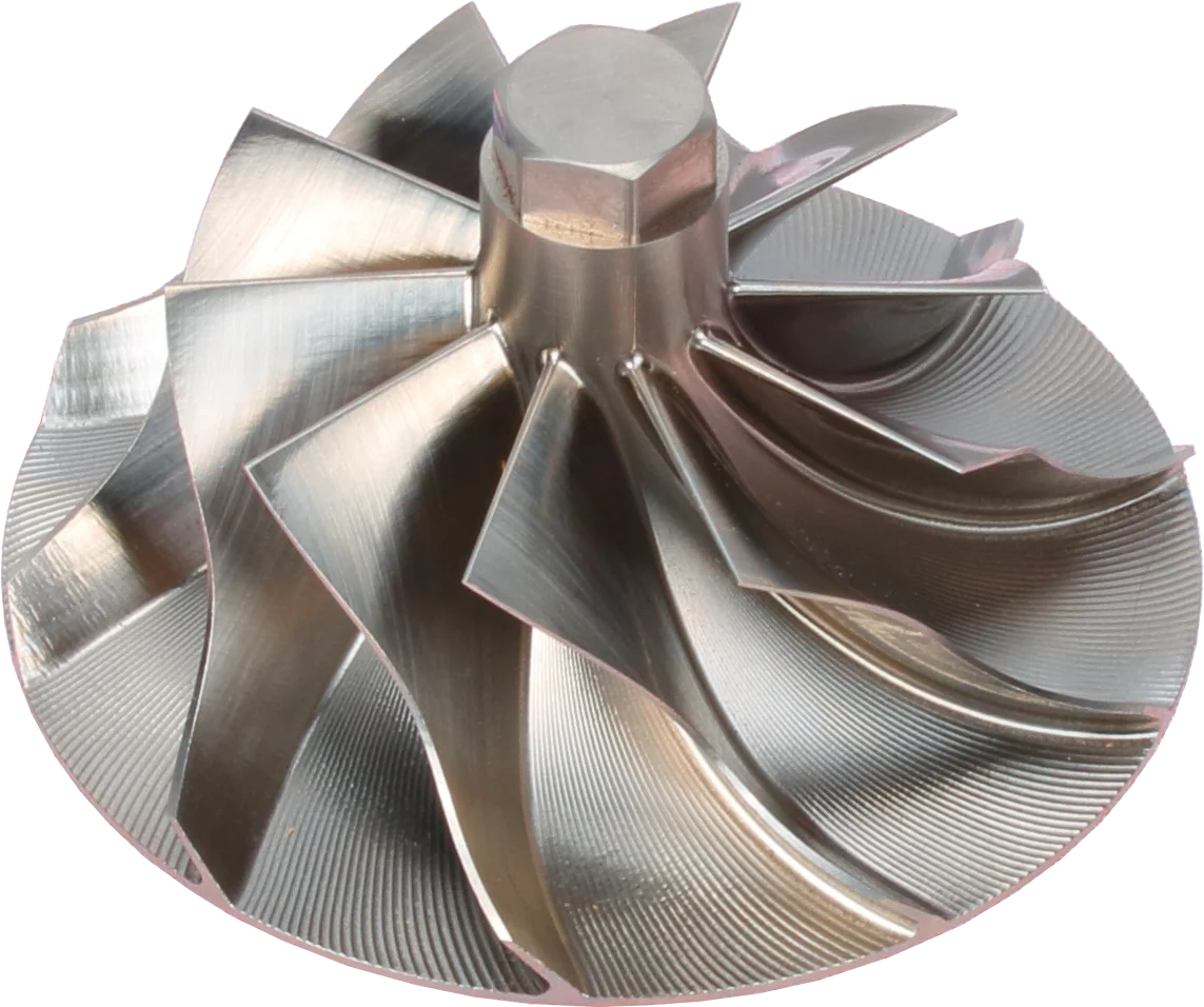
Blades: inspect for chips, bends and contact marks.
Hub: part of the balanced rotating assembly.
Outer blade tips: check for housing rub.
Product photograph from 2026. Numbers identify the features explained below.
Vaned vs vaneless turbocharger diffusers
The turbo diffuser surrounds the wheel's discharge. Depending on the assembly, its walls are formed by the compressor cover and backplate, and it may include a separate ring of stationary vanes.
| Type | Practical strength | Design trade-off |
|---|---|---|
| Vaneless | An open annular passage often supports a broad usable flow range | Comparable pressure recovery may need more space; peak efficiency can be lower than a suitably matched vaned design |
| Vaned | Shaped passages can provide strong pressure recovery and high peak efficiency in a compact package | Fixed vane angles are more sensitive to changes in incoming flow direction; the efficient operating range may narrow |
That is the basic trade-off between map width and peak efficiency. Here, map width means the usable flow range, not a guarantee of good performance everywhere. The wheel, diffuser dimensions, and complete compressor design still control the result. Neither type prevents surge: at low flow and high pressure ratio, either design can reach the point where flow reverses and pulses, and a vaned diffuser usually gets there sooner when flow moves away from its design point.
Why the housing shape matters
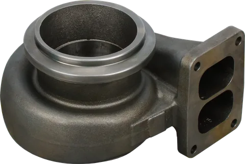
The compressor housing volute is the spiral collector around the diffuser. Its passage generally grows toward the outlet because it must carry air gathered from progressively more of the diffuser's circumference. It gathers that flow and can recover additional pressure as velocity decreases.
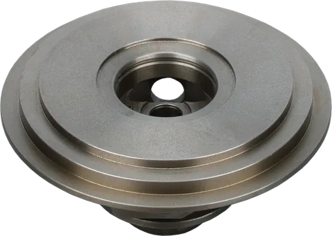
The housing also provides the closely fitted surface around the blade tips and may form one wall of the diffuser. Its internal machining therefore matters just as much as its hose connections. A cover can bolt onto a center section while having the wrong wheel contour or diffuser geometry.
Tip clearance and why rubbing marks matter
Tip clearance is the gap between the rotating blade tips and the stationary housing surface around them. It allows the intended operating movement and thermal growth while limiting leakage across the blade tips.
An excessive gap lets more air leak from a blade's side with higher pressure toward its side with lower pressure, wasting work and reducing efficiency. An insufficient gap can allow contact, which damages blade tips and the housing and can disturb rotor balance.
Rubbing marks show that contact has occurred. Your compressor wheel may rub because of excessive rotor movement, incorrect parts, poor housing seating, or distortion. Inspect the wheel, housing, and rotating assembly, then measure clearances using the manufacturer's specifications and method. Rubbing marks alone do not identify the cause, and free rotation by hand does not confirm clearance at operating speed and temperature. A shiny arc or circumferential groove does not identify the cause by itself.
Inspect the matching wheel surface and the rotating assembly before approving either part for reuse. Use the manufacturer's dimensions and measurement method; there is no universal acceptable clearance for diesel turbochargers. Turning the wheel freely by hand is a useful assembly check, but it cannot confirm clearance at operating speed and temperature.
How damage changes boost and efficiency
Different defects interrupt different parts of the compression process. Their effects can overlap, so low boost alone does not tell you whether the wheel, diffuser, or housing is responsible.
| Location | Damage or defect | Likely effect |
|---|---|---|
| Inducer | Bent, chipped, or eroded leading edges | Disturbed inlet flow and reduced efficiency; missing material also affects balance |
| Impeller and exducer | Damaged blades or worn tips | Less effective energy transfer, leakage, and possible imbalance |
| Diffuser | Heavy deposits, gouges, distorted walls, or damaged vanes | Altered passage area and poorer pressure recovery |
| Housing shroud | Scoring or an incorrect machined contour | Incorrect tip clearance, leakage, or renewed wheel contact |
| Volute and outlet | Cracks through the wall, damaged joints, or sealing defects | Escaping compressed air reduces delivered boost and increases the work needed to meet demand |
A boost control system may partly compensate for lost efficiency by increasing turbine drive. Depending on operating conditions, apparently normal boost can coexist with hotter discharge air or higher shaft speed. Judge the repair by more than the boost number.
What to check when replacing a housing or wheel
Treat the compressor as a matched assembly. Use these checks when deciding whether to replace only the cover, change the wheel, or install a CHRA.
Replacing only the housing can leave the balanced rotor intact when the service procedure permits it. Diesel turbocharger compressor wheel replacement involves the rotating assembly, so its inspection and balancing requirements also apply.
- Confirm the approved combination. Match the turbocharger assembly number to the specified wheel, housing, backplate, and CHRA. Casting numbers and wheel diameters help identify parts, but do not establish compatibility by themselves.
- Compare internal geometry. Check the wheel contour, axial position, housing centering register, and diffuser dimensions against service information. An apparently larger cover can change clearances and pressure recovery without improving usable airflow.
- Inspect every retained surface. Look for cracks, impact damage, scoring, deposits, and distorted mating faces. Remove contamination using an approved method, and verify that no debris remains in the diffuser or scroll.
- Measure and assemble to specification. Follow the specified clearance checks, sealing arrangement, fastener torque, and tightening sequence. Verify that the cover seats squarely and the wheel rotates without contact after assembly.
- Handle wheel changes as rotor work. Replacing a wheel changes the rotating assembly. Follow the required inspection and balancing process through a qualified rebuilder; alignment marks alone do not establish acceptable balance.
- Check outlet orientation and connections. Clock the housing as permitted by the assembly instructions. Reconnect any pressure references on the housing, and ensure intake and charge pipes fit without forcing the cover out of alignment.
- Verify the repair under load. Test the assembled charge air path for leaks using the equipment's procedure, then compare boost and relevant temperature readings with specified expectations under comparable operating conditions.
If a wheel has rubbed, establish why before fitting replacements. A new cover will not correct excessive rotor movement, and a new wheel will not restore a housing that exceeds its reuse limits.
Common Questions
Does the compressor wheel create pressure or just airspeed?
Both. The wheel adds energy that raises airspeed, pressure, and temperature. The diffuser and volute recover more static pressure as the air slows, without receiving shaft power.
Are inducer and exducer diameters enough to match a wheel?
No. Wheels with the same nominal diameters can have different blade profiles, heights, bores, backfaces, and housing clearance requirements. Match the approved part number and geometry for the turbocharger assembly.
Does a higher blade count mean better performance?
No. Blade count changes flow guidance, blockage, and friction. Splitter blades help manage these competing demands, but performance depends on the complete compressor design and its operating conditions.
Can a scored compressor housing be reused?
Reuse depends on the damage location, depth, and manufacturer's limits. Marks from wheel contact require investigation and dimensional inspection. Replacing the wheel alone does not restore a worn housing contour or correct the cause of contact.
Does a vaneless compressor still have a diffuser?
Yes. The open annular passage around the wheel acts as the diffuser. Air can slow and gain static pressure there without passing between stationary blades.
In simple terms, how does a turbo compressor work?
The turbine drives a compressor wheel that adds energy to intake air. Air enters through the inducer, moves outward through the impeller, slows in the diffuser, and collects in the volute before leaving for the engine.
Why is my turbocharger compressor wheel rubbing?
Your compressor wheel may rub because of excessive rotor movement, incorrect parts, poor housing seating, or distortion. Inspect the wheel, housing, and rotating assembly, then measure clearances using the manufacturer's specifications and method. Rubbing marks alone do not identify the cause, and free rotation by hand does not confirm clearance at operating speed and temperature.
Can I replace only the turbocharger housing?
Yes, you can replace only the housing when the service procedure permits it. Confirm that the housing matches the approved assembly and check its internal geometry, seating, and specified clearances. Inspect retained parts for damage before assembly. If the wheel has rubbed, find the cause first; a new housing will not correct excessive rotor movement.
For help matching a compressor wheel, housing, or CHRA, contact us with the turbocharger part number and engine details.