The essential difference in wastegate vs VGT turbocharger boost control is where the exhaust goes. A wastegate diverts some exhaust around the turbine wheel. A variable geometry turbo changes the passages that direct exhaust into that wheel.
Both regulate turbine power, but their mechanisms, failure patterns, and replacement requirements differ.
Why Boost Must Be Regulated
A turbocharger uses exhaust energy to drive a compressor. As engine load and exhaust flow change, the energy available to the turbine changes too. The engine does not need maximum boost in every condition.
Turbo boost control helps deliver the requested airflow while keeping turbo speed, pressure, and operating temperatures within the intended limits. Excessive boost can put the engine and turbocharger under damaging loads. Insufficient boost can reduce power and, depending on the engine and its controls, contribute to smoke or other operating problems.
On electronically managed engines, the controller uses pressure readings and other inputs to adjust turbo operation. Its target varies with operating conditions rather than staying at one fixed pressure.
Overboost and underboost describe a mismatch, not a diagnosis. A pressure fault may come from the turbo mechanism, an actuator, a leak, a sensor, or another engine-system problem.
How do wastegate vs VGT controls compare?
| Feature | Wastegate turbo | Variable geometry turbo |
|---|---|---|
| Main control method | Bypasses exhaust around the turbine wheel | Changes turbine inlet passage area and flow direction |
| Moving hardware | Bypass valve, shaft, and linkage | Typically adjustable vanes and a mechanism that moves them together |
| Actuator options | Pressure, vacuum, or electronic, depending on design | Vacuum or electronic, depending on design |
| Typical mechanical trouble | Sticking valve, worn linkage, poor valve sealing | Soot-related sticking, corrosion, or mechanism wear |
| Replacement concern | Correct actuator travel and specified rod setting | Correct actuator compatibility and geometry calibration |
Actuator type alone does not identify the turbo design. An electronic actuator may operate either a wastegate or variable geometry.
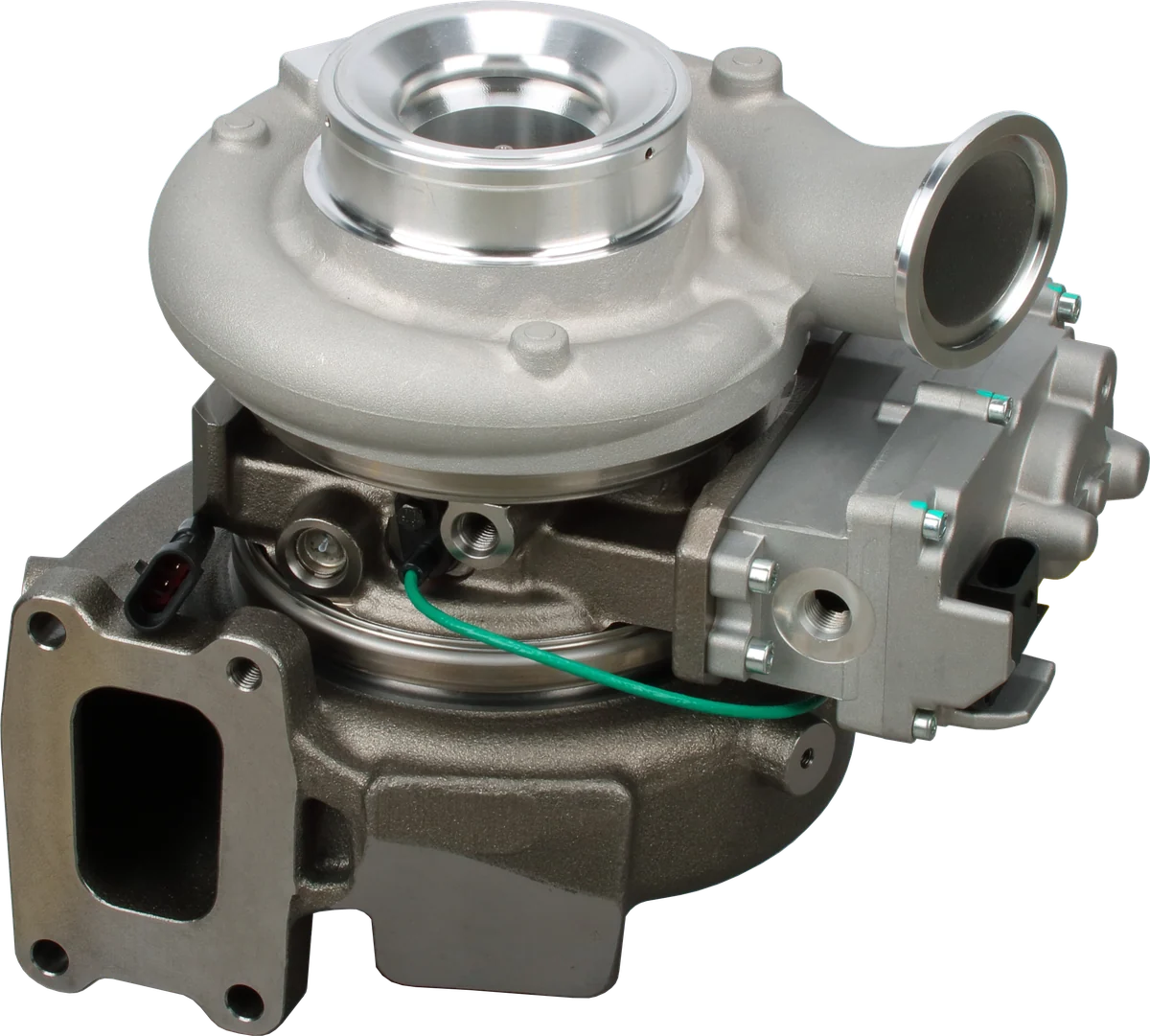
Compressor housing: guides the compressed air.
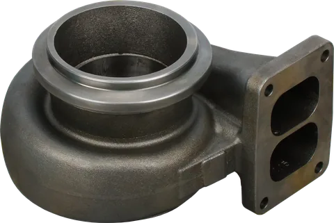
Turbine housing: guides exhaust gas to the turbine.
Actuator: check its type, linkage and calibration.
Product photograph from 2026. Numbers identify the features explained below.
How Does a Turbocharger Wastegate Work?
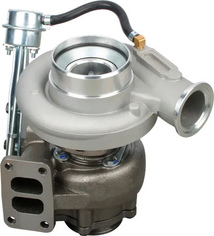
A wastegate opens a passage that lets some exhaust bypass the turbine wheel. Sending less exhaust through the wheel reduces the power available to drive the compressor.
Closing the bypass directs more exhaust through the turbine. Opening it helps limit turbine power as operating conditions demand. The valve can take intermediate positions; it is not simply an on/off device.
A wastegate handles exhaust gas. It does not release compressed intake air like a compressor bypass or blow-off valve.
Pneumatic actuators
A pneumatic actuator uses pressure or vacuum acting on a diaphragm, usually against a spring, to move a rod connected to the wastegate.
In a common pressure-operated arrangement, rising control pressure pushes the wastegate toward opening. An engine-controlled solenoid can modify that pressure signal. Vacuum-operated systems use a vacuum supply and control valve instead.
Do not assume every rod moves in the same direction or that loss of vacuum always produces the same boost result. Check the application’s operating description.
Electronic actuators
An electronic wastegate actuator uses a motor and gearing to position the valve. Position feedback lets the controller monitor whether the mechanism follows its command.
Possible faults include damaged gears, wiring problems, internal electronics failure, and a binding wastegate that overloads an otherwise functional actuator.
How Does a VGT Turbocharger Work?
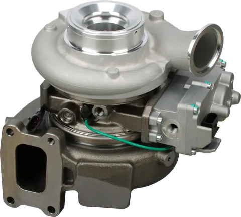
A variable geometry turbo changes how exhaust enters the turbine wheel. Many designs use adjustable vanes around the turbine inlet, linked so they move together.
At lower exhaust flow, a narrower effective passage can increase gas velocity and direct flow to produce useful turbine torque. As flow rises, the mechanism generally opens the passages to accommodate more exhaust and manage turbine power and exhaust backpressure.
Actual commands depend on the engine’s operating strategy. For a diesel variable geometry turbocharger, geometry control can also support exhaust gas recirculation or exhaust braking in some applications. Vane position therefore cannot always be predicted from boost pressure alone.
A VNT turbo, meaning variable nozzle turbine, belongs to this general family. Neither label establishes actuator compatibility.
Soot deposits can restrict vane or linkage movement. Heat, corrosion, and wear can also cause binding. A mechanism that moves when cold may still stick after warming up or under operating loads.
Where Twin-Scroll and Two-Stage Systems Fit
Twin-scroll describes a divided turbine inlet that keeps selected exhaust pulses separated on their way to the turbine. With a suitable exhaust manifold, this helps preserve pulse energy and improve response.
Twin-scroll is not a boost-control actuator type. A twin-scroll turbo may still use a wastegate.
A two-stage turbo system uses two turbochargers to share the compression work. In a series arrangement, air passes through one compressor and then the other. Bypass valves and other controls manage how the stages contribute across operating conditions.
Not every two-turbo installation is two-stage; two turbos can also operate in parallel. On a two-stage system, a bypass fault or leak between stages can resemble a failed turbo, so diagnosis must cover the complete system.
Common Failures and Their Symptoms
A sticking mechanism can produce underboost, overboost, or unstable response depending on where it binds. The controller may reduce engine power or enter limp mode when actual pressure or actuator position departs from its expected range.
| Suspected fault | What it can cause | Useful inspection direction |
|---|---|---|
| Soot-bound VGT vanes | Slow response, pressure overshoot, intermittent limp mode | Check commanded versus actual position and mechanical travel |
| Sticking or poorly sealing wastegate | Underboost when open or leaking; overboost when unable to open | Inspect valve movement, linkage, and sealing |
| Vacuum or pressure-control leak | Incorrect actuator movement | Check hoses, supply, diaphragm, and control solenoid |
| Charge-air leak | Underboost, hissing, reduced power | Inspect and test pipes, boots, and intercooler |
| Position sensor or wiring fault | Implausible feedback, control faults, reduced power | Check connectors, wiring, and position data |
| Incorrect actuator setting | Persistent boost errors, limited travel, failed learning procedure | Verify part compatibility and required calibration |
The actuator position sensor and intake pressure sensor serve different purposes. One reports mechanism position; the other helps report the pressure result. Either can create misleading diagnostic evidence.
A hiss or whistle alone cannot identify a control fault. Use the broader checks in How to Diagnose a Failed Turbocharger Before Replacement before condemning the assembly.
A Practical Boost-Control Inspection Sequence
Start with evidence before changing parts or adjusting linkages.
- Record fault codes and freeze-frame data. Note whether the complaint occurs cold, hot, during acceleration, or under sustained load. A code identifies the detected condition, not necessarily the failed component.
- Inspect the intake and charge-air path. Look for split boots, loose clamps, damaged pipes, and intercooler leaks. Use the vehicle’s specified leak-test method and pressure.
- Check pneumatic controls where fitted. Verify hose routing, vacuum supply or pressure signal, solenoid operation, and actuator response using the specified test equipment and limits.
- Inspect wiring and connectors. Look for heat damage, corrosion, loose terminals, and harness rubbing near the actuator and sensors.
- Compare commanded and actual readings. Where supported, graph requested pressure, measured pressure, actuator command, and position feedback under the conditions that trigger the fault.
- Check mechanical travel by the approved procedure. Binding, lost motion, or incomplete travel matters. Do not force electronic actuator gears or alter factory stops.
- Consider the rest of the engine. Exhaust leaks upstream of the turbine, exhaust restrictions, and airflow or fueling problems can affect boost.
Compare pressure values on the same basis: a scan tool may display absolute pressure while a boost gauge shows pressure above atmospheric pressure.
If position follows its command but boost remains low, investigate airflow, leaks, sensors, and engine conditions. If position fails to follow, investigate the actuator, wiring, and driven mechanism.
Avoid repeated heavy-load testing when overboost is occurring. Continuing to demand boost through a substantial charge-air leak can also push the turbo harder as the controller tries to recover pressure.
Why Electronic Turbocharger Actuator Calibration Matters
Installing an actuator establishes a mechanical connection, but the control system also needs the correct relationship between commanded position and actual valve or vane movement.
That relationship includes the usable travel range, reference positions, and sometimes a specified turbine-flow setting. An actuator bolted onto the housing can look correct while positioning the mechanism incorrectly.
Depending on the application, replacement may require:
- Bench matching or flow calibration of the actuator and turbo.
- A scan-tool initialization or position-learning routine.
- Compatible actuator software or application-specific programming.
These procedures are not interchangeable. A vehicle relearn cannot necessarily correct an incorrectly assembled linkage or substitute for required bench calibration.
Likewise, a “pre-calibrated” assembly may still require installation checks or a vehicle learning procedure. Confirm what the supplier has completed and what remains necessary.
If learning fails, check compatibility, supply voltage, wiring, and free mechanism movement. Repeatedly running the routine will not cure binding vanes.
Match the Actuator and Setting Before Ordering
When comparing wastegate vs VGT, identify the turbocharger itself as well as the vehicle. Year, engine displacement, and a matching electrical connector may not distinguish every version.
Use How to Identify a Turbocharger Part Number, then confirm the application with How to Verify Turbo Fitment Before Ordering.
Before ordering, confirm:
- Turbo and actuator part numbers, including applicable revisions.
- Wastegate or variable geometry design.
- Pressure, vacuum, or electronic actuation.
- Correct bracket, linkage, connector, and specified setting.
- Whether the actuator is included, matched, and calibrated.
- Any required installation learning or programming.
When considering a separate replacement actuator, establish that the mechanism it drives is serviceable. Replacing the motor on a binding turbo may leave the original problem unresolved.
A core replacement also has limits. CHRA vs Complete Turbocharger explains why replacing the rotating assembly does not automatically repair external control hardware.
Common Questions
Is a VGT better than a wastegate turbo?
A VGT can provide responsive boost across a wider operating range, but its moving geometry adds complexity. A wastegate turbo can work very well when matched to its engine. For a stock replacement, use the specified turbo and control system.
Are VNT and VGT the same thing?
Both terms describe variable turbine geometry used to control exhaust flow through the turbine. VNT refers to variable nozzle turbine designs. The terminology does not establish fitment: housings, mechanisms, actuators, and control requirements can differ.
Can a stuck wastegate cause underboost and overboost?
Yes. A wastegate stuck open can bypass too much exhaust and cause underboost. One stuck closed can prevent sufficient bypass and cause overboost under load. Partial sticking may cause intermittent faults.
Does every electronic turbo actuator need programming?
No. Depending on the application, an actuator may need mechanical calibration, an electronic position learn, software programming, or a combination. Some assemblies arrive matched and calibrated, but installation may still require a vehicle-specific procedure.
Can I adjust the actuator rod to fix low boost?
Do not use rod adjustment as a general repair. It changes the relationship between actuator movement and the wastegate or vane mechanism. First identify the fault, then follow the specified setting procedure if adjustment is permitted.
Will replacing the CHRA fix sticking VGT vanes?
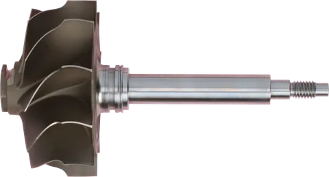
Usually not. The CHRA contains the rotating assembly and bearing housing; the variable geometry mechanism is generally separate. Diagnose the vanes, linkage, and actuator before deciding whether a core, actuator, or complete turbo is appropriate.
What causes turbocharger overboost?
A wastegate that cannot open or VGT vanes that stick from soot can cause overboost. Check valve or vane movement, linkage, and commanded versus actual actuator position. A pressure fault does not identify the failed part, so inspect the controls and sensors before replacing the turbo.
Which replacement turbocharger actuator do I need?
Choose an actuator that matches your turbo and actuator part numbers, turbo design, actuation type, bracket, linkage, connector, and specified setting. A matching connector alone does not confirm compatibility. Before ordering, verify that the mechanism it drives is serviceable and confirm any required calibration, position learning, or programming.
For help with wastegate vs VGT replacement selection, contact LeadTurbo with your turbo part number, actuator details, fault codes, and symptoms.