A diesel pickup with two turbos may feel weak leaving a stop, lose power under sustained load, or hesitate as airflow demand increases. Those symptoms do not automatically mean that either turbo needs replacing. A control valve, leaking connection, or misleading sensor can disrupt the entire system.
The starting point is identifying how the two units work together.
Why One Turbo Cannot Do Everything
A turbocharger must respond to changing exhaust energy while supplying the engine with enough air across its operating range. Choosing its size involves compromises.
A smaller turbo generally accelerates quickly because its rotating assembly has less inertia, and its turbine can extract useful power from relatively modest exhaust flow. That helps low-speed response. At higher demand, however, its compressor can approach its flow limit, while its turbine becomes an exhaust restriction. Asking for more boost cannot create unlimited airflow.
A larger turbo can handle greater airflow efficiently when properly matched. At low engine load and speed, it may take longer to accelerate because exhaust energy is limited and the rotating assembly requires more energy to speed up.
Two turbochargers let designers distribute that work. Sizing still matters in a two stage diesel turbocharger system, but valves and controls expand the usable operating range. Our guide to what causes turbo lag explains the response side in more detail.
Series vs Parallel Turbocharger Systems: Two-Stage, Sequential, and Twin Turbo
These terms describe different aspects of a system and are sometimes used loosely.
| Arrangement | How intake air moves | How the turbos contribute |
|---|---|---|
| Series two-stage, often called compound turbocharging | Air passes through one compressor and then the other | Both stages can contribute to the final pressure rise |
| Parallel sequential | Separate compressor branches feed a common intake | One turbo handles lower demand; the second is progressively brought into useful operation |
| Parallel simultaneous | Separate compressor branches feed a common intake | Both turbos normally contribute together |
A two stage turbocharger system usually means a series arrangement with a high-pressure and a low-pressure unit. “Sequential turbo” describes an operating strategy, so the term alone does not establish the plumbing layout.
Likewise, “twin turbo diesel” only establishes that two turbos are present. Trace the intake pipes or consult the service diagram before applying a diagnostic explanation.
In aftermarket diesel discussions, “compound turbo” commonly means series compression. This differs from turbocompounding, where an additional turbine recovers exhaust energy for mechanical or electrical output.
How does a two stage turbocharger work with HP and LP units?
In a typical high-pressure and low-pressure turbocharger arrangement, fresh air enters the larger low-pressure, or LP, compressor first. It then travels to the smaller high-pressure, or HP, compressor, which raises its pressure further before the air reaches the engine through the charge-air system.
Exhaust generally travels in the opposite stage order: from the engine through the HP turbine, then through the LP turbine. Bypass passages modify that route.
The names describe the stages' positions and operating pressure levels. They do not mean the LP turbo is unimportant or only produces boost at low engine speed.
When both compressors contribute, their pressure ratios compound. Pressure ratio compares absolute outlet pressure with absolute inlet pressure. You cannot simply add two gauge-pressure readings and treat the result as the system's compression ratio; connecting pipes and coolers also introduce pressure losses.
How bypass and regulating valves change the workload
At lower airflow demand, the controls commonly direct exhaust through the smaller HP turbine to build response. The LP unit may still rotate and contribute. Saying that one turbo is “off” can therefore be misleading.
As demand rises, an exhaust bypass around the HP turbine can send more exhaust energy directly toward the LP turbine. Where fitted, a compressor bypass allows charge air to avoid the smaller HP compressor when it would become restrictive.
Depending on the design, regulation may also involve:
- A wastegate that diverts exhaust around a turbine.
- Variable turbine geometry that changes how exhaust acts on the wheel.
- Pneumatic or electronic actuators that position the valves.
- Pressure, temperature, airflow, and position sensors that inform the controller.
Valve movement is often gradual and coordinated. There is no universal “all valves open” high-speed mode. Use the engine-specific flow diagram and control procedure; the wastegate and VGT guide explains those individual mechanisms.
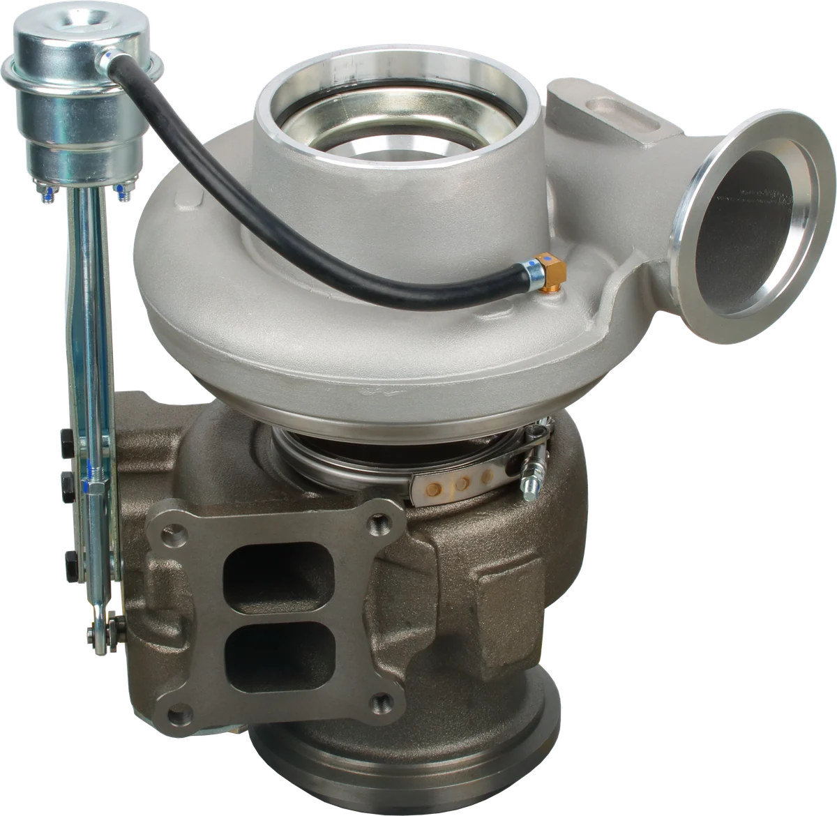
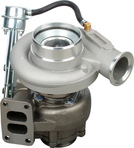
Compressor housing: guides the compressed air.
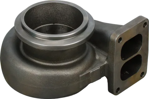
Turbine housing: guides exhaust gas to the turbine.
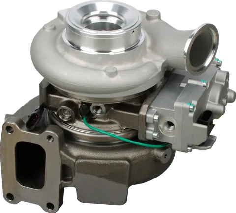
Actuator: check its type, linkage and calibration.
Product photograph from 2026. Numbers identify the features explained below.
How Parallel Sequential Turbocharging Switches
In a parallel sequential system, one turbo initially supplies most of the useful airflow. Valves limit the second turbo's participation until demand increases.
A typical transition admits exhaust to accelerate the second turbo before fully connecting its compressor outlet to the shared intake. Coordinating those actions helps avoid a pressure disturbance or reverse flow through an inactive branch.
At higher demand, both compressors supply air through parallel paths. Unlike series compression, the same air does not normally pass through both compressors in succession.
The exact valve sequence depends on the design. Engine load matters as well as RPM: light cruising and heavy acceleration at the same engine speed can require different valve positions. A hesitation during the transition calls for checking control operation, rather than assuming the second turbo has failed.
Where Interstage Cooling Fits
Compression heats intake air. An interstage cooler, when fitted between the LP and HP compressors, reduces the temperature of the air entering the second stage. This can reduce the compression work required there.
A final charge-air cooler removes heat before the air enters the engine. Not every two-stage system has a separate interstage cooler.
During diagnosis, distinguish cooler locations. A restriction or leak between compressors affects the HP inlet conditions; a fault after the HP compressor affects the final delivery path.
Typical Failure Points and What They Can Look Like
Symptoms overlap, so use this table to choose checks rather than to condemn a component.
| Possible fault | Possible behavior | Useful inspection |
|---|---|---|
| Sticking bypass or regulating valve | Weak low-speed boost, hesitation, overboost, or poor high-flow performance | Check commanded position, actual movement, and valve seating |
| Failed actuator or loose linkage | Intermittent response or failure to change operating mode | Inspect supply hoses, wiring, pivots, rods, and attachment points |
| Biased pressure or airflow sensor | Incorrect boost control, derating, or implausible readings | Compare related readings under known conditions |
| Leak between compressor stages | Reduced final boost, hiss, or oily residue at a connection | Test interstage pipes, seals, and any cooler |
| Exhaust leak before a turbine | Slow boost response or weak power | Look for soot trails and damaged joints |
| Wear or damage in one turbo | Noise, oil leakage, or poor pressure contribution | Inspect both units and their oil supply and drain systems |
One weakened stage can change the other stage's workload. For example, reduced LP delivery can leave the HP compressor needing a greater pressure ratio to reach the same final pressure. Whether it actually does so depends on the controls and operating limits.
The system may instead reduce engine output. Either way, replacing the visibly damaged turbo without investigating the whole system can leave the cause unresolved.
A Practical Diagnostic Sequence
Start with the vehicle's service information. Underboost and overboost codes describe a measured condition; they rarely identify a failed turbo by themselves.
1. Record when the problem happens.
- Is response poor from low speed, only during transition, or under sustained load?
- Does it occur cold, hot, intermittently, or after recent repairs?
- Are there stored codes and freeze-frame data?
- Does the problem involve noise, smoke, oil consumption, or only reduced power?
2. Inspect the complete flow path.
Check the air filter and inlet ducts, both compressor connections, interstage plumbing, charge-air cooler, and intake manifold connections. Inspect exhaust joints that supply the turbines.
Pressure-test or smoke-test the relevant sections using the manufacturer's procedure and limits. A connection may seal at rest but leak under boost. Oily residue helps locate a suspect joint, but it does not prove internal turbo failure.
3. Verify controls and sensor readings.
Check vacuum or pressure supplies where used, electrical connectors, and linkage attachment. With suitable diagnostic equipment, compare commanded actuator positions with reported or observed movement.
A moving actuator does not prove the valve inside is seating correctly. Avoid forcing electronic actuators or changing rod lengths to chase a boost symptom.
Compare pressure readings under the service procedure's specified conditions. Confirm whether each reading is absolute or gauge pressure before interpreting it.
4. Evaluate stage contribution under controlled load.
Where sensors or approved test ports allow, compare LP outlet or HP inlet pressure with final charge pressure. Review these alongside engine load, airflow, and valve commands. Manifold boost alone cannot show how the pressure rise is divided or identify which turbocharger is causing low boost.
Avoid repeated hard acceleration if there is scraping noise, heavy smoke, or rapidly increasing oil consumption.
5. Inspect mechanically when the evidence points there.
With the engine stopped and cool, inspect accessible wheels for damage or housing contact and assess shaft movement against the correct specifications. Also check oil feed restrictions, drains, and crankcase ventilation. The turbo diagnosis guide provides a broader inspection framework.
Before Ordering: Identify HP or LP and the Exact Part Number
For a two stage turbocharger replacement, do not order using “small turbo,” “front turbo,” or engine displacement alone. Position descriptions can be ambiguous, and similar housings can contain different wheels, controls, or calibrations.
Record:
- Vehicle year, engine identification, VIN, and relevant build details.
- Whether the failed unit is HP or LP according to the service diagram.
- The identification number on each turbo, with clear label photographs.
- Actuator identification and whether the unit is supplied separately or as an assembly.
Use how to identify a turbocharger part number and how to verify turbo fitment before purchasing.
A CHRA replacement will not correct a damaged housing or sticking external bypass mechanism. Review CHRA versus complete turbocharger when deciding repair scope. Inspect the companion turbo and clean or replace contaminated connecting components as required before installation.
Common Questions
Are two-stage, sequential, and twin turbos the same?
No. Two-stage usually describes compressors working in series. Sequential describes bringing turbo capacity into use progressively. Twin turbo only tells you there are two turbos; it does not identify the airflow arrangement.
Which turbo is the high-pressure unit?
In a typical series system, the HP turbo is the smaller unit whose compressor receives air from the LP compressor and raises its pressure further. Confirm identification using the engine's service diagram and each turbo's part number.
At what RPM does the second turbo turn on?
There is no universal switching RPM. Control depends on engine load, speed, operating conditions, and calibration. In many series systems, both turbos already rotate while valves gradually change how much work each performs.
Can a sticking bypass valve cause low boost?
Yes. A valve stuck open can divert flow needed for boost, while one stuck closed can restrict flow or cause excessive boost under other conditions. The result depends on the valve's location and the operating mode.
Does the other turbocharger need replacement when one fails?
Not automatically. Inspect both units, shared lubrication systems, and connecting passages. Replace the other turbo only if inspection supports it or the manufacturer requires assembly replacement. Debris or a shared oil problem can damage both.
Can one boost sensor identify the failed turbo?
Usually not. Manifold pressure shows the combined system result. Identifying the faulty stage requires checking valve operation, leaks, sensor plausibility, and available pressure readings between stages, followed by mechanical inspection when necessary.
Need help identifying a replacement for your two stage turbocharger system? Contact LeadTurbo with your turbo part number, vehicle details, and symptoms so we can help check the appropriate unit.